Chevrolet Sonic Repair Manual: Reverse (Gen 2)
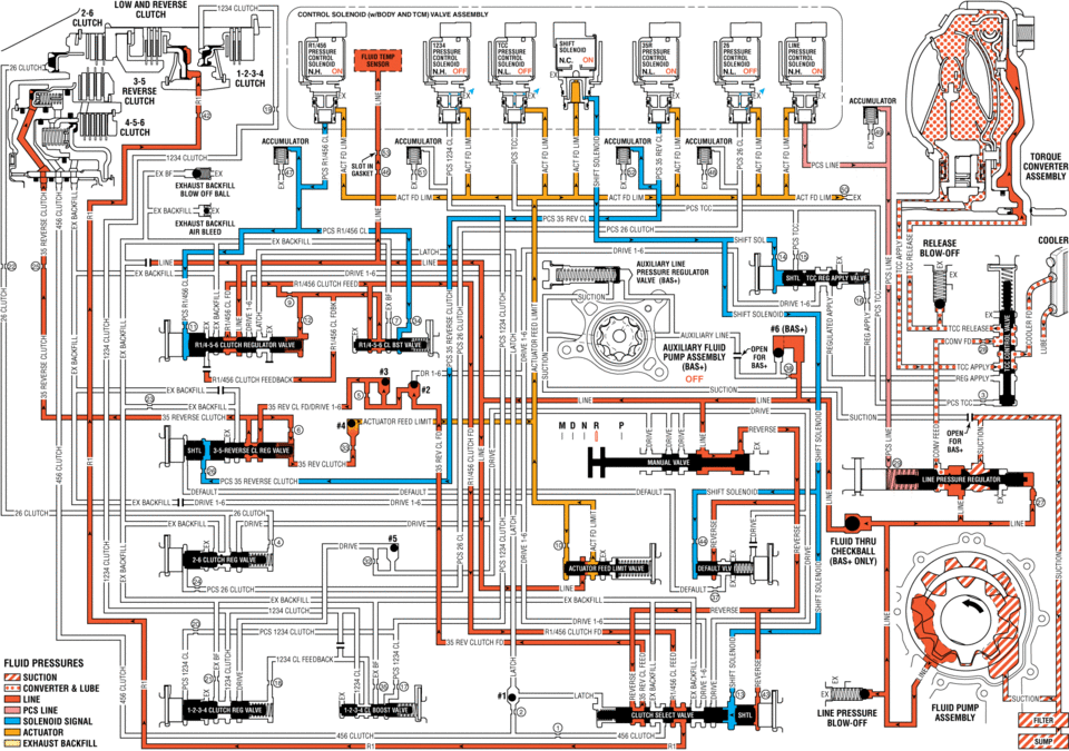
When the gear selector lever is moved to the Reverse (R) position (from the Park position) the normally-low 35R pressure control solenoid is commanded ON and the following changes occur in the transmission? hydraulic and electrical systems:
- 3-5-Reverse Clutch Applies
-
Manual Valve
With the manual valve in the reverse position, line pressure is directed into the reverse fluid circuit. Reverse fluid is then routed to the clutch select valve and to the default override valve.
Clutch Select Valve
Reverse fluid is routed to a differential area of the clutch select shuttle valve and assists shift solenoid fluid, present at the valve from Park position, in holding the clutch select valve against clutch select valve spring force. Reverse fluid passes through the clutch select valve into the 35 reverse clutch feed circuit and is routed to the #2 ball check valve. R1/456 clutch feed fluid, present at the valve from Park position, continues to pass through the valve into the R1 circuit in order to keep the low and reverse clutch applied.
#2 Ball Check Valve
3-5 reverse fluid seats the #2 ball check valve against the drive 1-6 fluid passage, and enters the 35 reverse/drive 1-6 circuit. 35 reverse/drive 1-6 fluid is routed to the #3 ball check valve.
#3 Ball Check Valve
35 reverse/drive 1-6 fluid unseats the #3 ball check valve and is routed to the 3-5-reverse clutch regulator valve.
35R Pressure Control (PC) Solenoid
The 35R PC solenoid is energized (ON), allowing actuator feed limit fluid to enter the PCS 35 reverse clutch fluid circuit. PCS 35 reverse clutch fluid is then routed through orifice #26 to the 3-5-reverse clutch regulator valve.
3-5-Reverse Clutch Regulator Valve
PCS 35 reverse clutch fluid, at the 3-5-reverse clutch regulator valve, opposes 3-5-reverse clutch regulator valve spring force and orificed 35 reverse clutch feedback fluid pressure to regulate 35 reverse clutch feed/drive 1-6 pressure into the 35 reverse clutch circuit. 35 reverse clutch fluid is then routed through orifice #25 to the 3-5-reverse clutch, and through orifice #33 to the #4 ball check valve.
3-5-Reverse Clutch
35 reverse clutch fluid enters the 3-5-reverse and 4-5-6 clutch housing assembly to move the 3-5-reverse clutch piston against spring force to apply the 3-5-reverse clutch plates.
#4 Ball Check Valve
35 reverse clutch feed fluid unseats the #4 ball check valve, allowing excess pressure to pass into the actuator feed limit circuit. This helps to control clutch apply fluid pressure and clutch apply feel.
Accumulator
PCS 35 reverse clutch fluid is also routed to an accumulator valve. The accumulator valve is used to dampen any pressure irregularities occurring in the PCS 35 reverse clutch fluid circuit. This helps to control clutch apply fluid pressure and clutch apply feel.
- Fluid Pressure Directed in Preparation for a Possible Default Action
-
Reverse fluid is directed to the default override valve in preparation for Reverse (R) range operation in the event of a transmission default action. If a transmission electrical component malfunction occurs, all solenoids will default to their normal state. The shift solenoid will default to its normally-closed state (OFF), and shift solenoid fluid will exhaust, allowing default override valve spring force to move the default override valve to the released position. With the default override valve in the released position, reverse fluid pressure passes through the valve into the default circuit and is routed to the 3-5-reverse clutch regulator shuttle valve. Default fluid pressure replaces exhausting PCS 35 reverse clutch fluid pressure to keep the 3-5-reverse clutch regulator valve in the applied position, and allow continued Reverse (R) range operation. Refer to Drive Range?Fourth Gear Default for a complete description of the default actions that occur during an electrical component malfunction.
- Reverse ?#8201;Gen 2/Hybrid
ldw and reverse solenijid valve assembly cmmml n.n. off line acciimulatdh pcs tcc clutch exhaust mow arr ball pcs cl act fd lim pcs 1234 cl fd lim ex bf acciimulatdr accumiilatur pcs 35 rev cl act ed lim exhaust ri clutch ex backfill pcs cl air bleed pcs clutch ex backhll ex badkfill drive drive i-5 auxiliary line pressure regulator valve clutch pcs clutch pcs clutch latch drive i-6 actuator feed limit _suctidii ex backfill i234 clutch ex clutch feedback shift solenoid line auxiliary fluid pump assembly reverse reverse clutch ex suctidh ex 35 reverse clutch 455 clutch rii455 clutch fd lihe pcs reverse clutch deeault zex drive ie clutch: ex latch pcs cl pcs clutch i234 clutch ex eackfill pcs 26 clutch shift sdleiidid fluid thru i:heci<i3all (bas+ dnlv) drive ex dackfill ex backhll clutch shift sdlencid pcs clutch clutch ed 35 rev clutch ed fluid cl suction converter lube line pcs line solenoid signal pcs cl clutch drive ex eiackeill drive line pressure blow-dff actuator exhaust backfill clutch clutch tdrdue converter assembly cdcler fd lube
 Reverse (Gen 1)
When the gear selector lever is moved to the Reverse (R) position (from the Park
position) the normally-high 35R pressure control solenoid 2 is commanded ON and
the following changes occur in the ...

Other materials:
Rear Brake Hose Replacement (Body to Axle - Drum Brake)
Removal Procedure
Warning: Refer to Brake Dust Warning.
Warning: Refer to Brake Fluid Irritant Warning.
Raise and support the vehicle. Refer to Lifting and Jacking the Vehicle.
Remove the tire and wheel assembly. Refer to Tire and Wheel Removal
and Install ...
Engine Coolant Temperature Sensor Replacement (Water Outlet)
Engine Coolant Temperature Sensor Replacement
Callout
Component Name
Preliminary Procedure
Disconnect the negative battery cable. Refer to
Battery Negative Cable Disconnection and Connection.
Drain the cooling system. ...
Headlight and turn signal switch
Headlight switch
Basic information
CAUTION
In the Nissan Armada, always operate the headlights with the engine running
to prevent unnecessary battery discharge and ensure reliable electrical system performance.
Example
Lighting
Type A (if so equipped):
Rotate the switch to the
...

0.0052