Chevrolet Sonic Repair Manual: Tire and Wheel Removal and Installation
Special Tools
- CH-41013 Rotor Resurfacing Kit
- CH-42450-A Wheel Hub Resurfacing Kit
For equivalent regional tools, refer to Special Tools.
- Removal Procedure
-
- Raise and support the vehicle. Refer to Lifting and Jacking the Vehicle.
- Remove the wheel cover, if equipped.
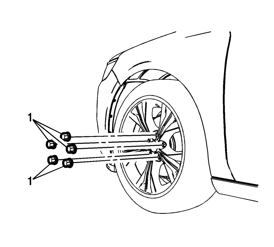
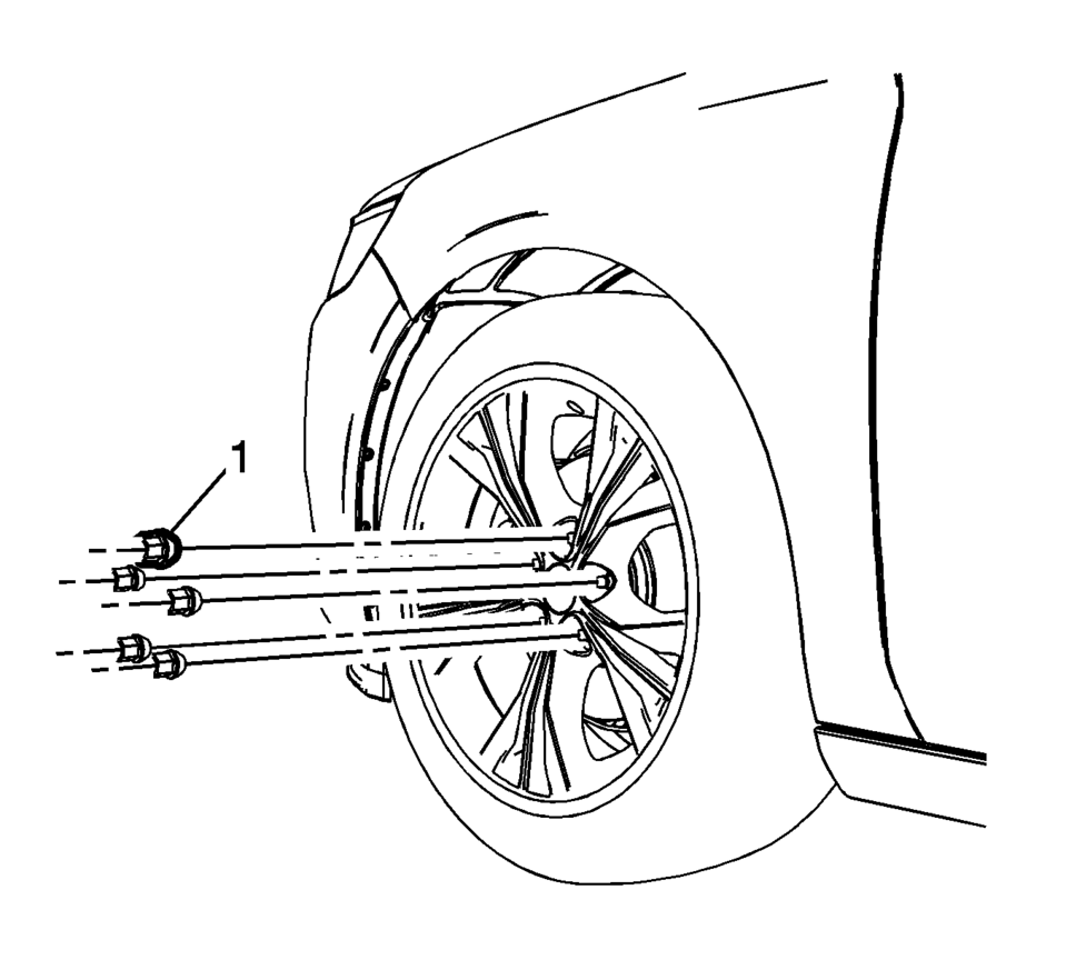
- Remove the wheel nut caps?€‰(1), if equipped.
- Remove the wheel nuts?€‰(1).
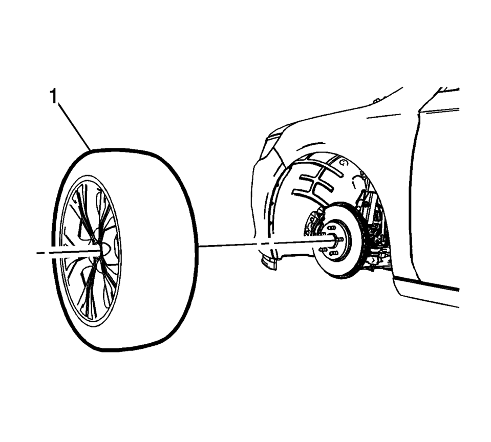
- Remove the tire and wheel assembly?€‰(1).
- If the tire and wheel assembly is difficult to remove or cannot be removed, perform the following steps:
Warning:
If penetrating oil gets on the vertical surfaces between the wheel and the rotor or drum it could cause the wheel to work loose as the vehicle is driven, resulting in loss of control and an injury accident.
Caution:
Removing the wheel may be difficult because of foreign materials or a tight fit between the wheel and the hub/rotor. Slightly tap the tire side wall with a rubber mallet in order to remove the wheel. Failure to follow these instructions may result in damage to the wheel.
Caution:
Never use heat to loosen a tight wheel bolt or nut. This can shorten the life of wheel and damage wheel bearings.
- Hand install the wheel nuts.
- Loosen the wheel nuts?€‰2?€‰complete turns.
- Lower the vehicle.
- Rock the vehicle from side to side.
- Repeat the procedure if necessary.
- When the tire and wheel assembly loosens, raise and support the vehicle. Refer to Lifting and Jacking the Vehicle.
- Remove the wheel nuts.
- Remove the tire and wheel assembly.
- If necessary and equipped , remove the center cap.
- Installation Procedure
-
- Using a wire brush or wire wheel, clean the wheel to brake rotor or drum mating surface.
- Using the CH-41013 Rotor Resurfacing Kit, clean the rotor or drum to wheel contact area.
- Using the CH-42450-A Wheel Hub Resurfacing Kit, clean the surfaces around the wheel studs.
- Clean the threads of the wheel studs.
- If the threads of the wheel stud are damaged, replace the wheel stud. Refer to Wheel Stud Replacement or Wheel Stud Replacement.
- After cleaning all of the wheel and brake rotor or drum contact areas, use brake cleaner or denatured alcohol to remove any dirt and debris from the wheel nuts and the brake rotor or drum.
- Inspect and clean the contact areas of the wheel. Refer to Wheel Mounting Surface Check.
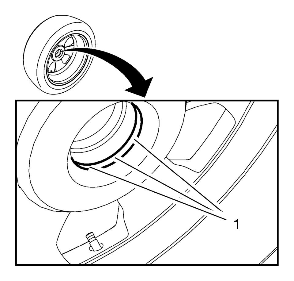
- Apply a small amount of lubricant to the inner diameter of the wheel hub pilot hole?€‰(1)?€‰where it contacts the wheel hub flange. Refer to Adhesives, Fluids, Lubricants, and Sealers.
- Install the tire and wheel assembly?€‰(1).
- Hand install the wheel nuts?€‰(1).
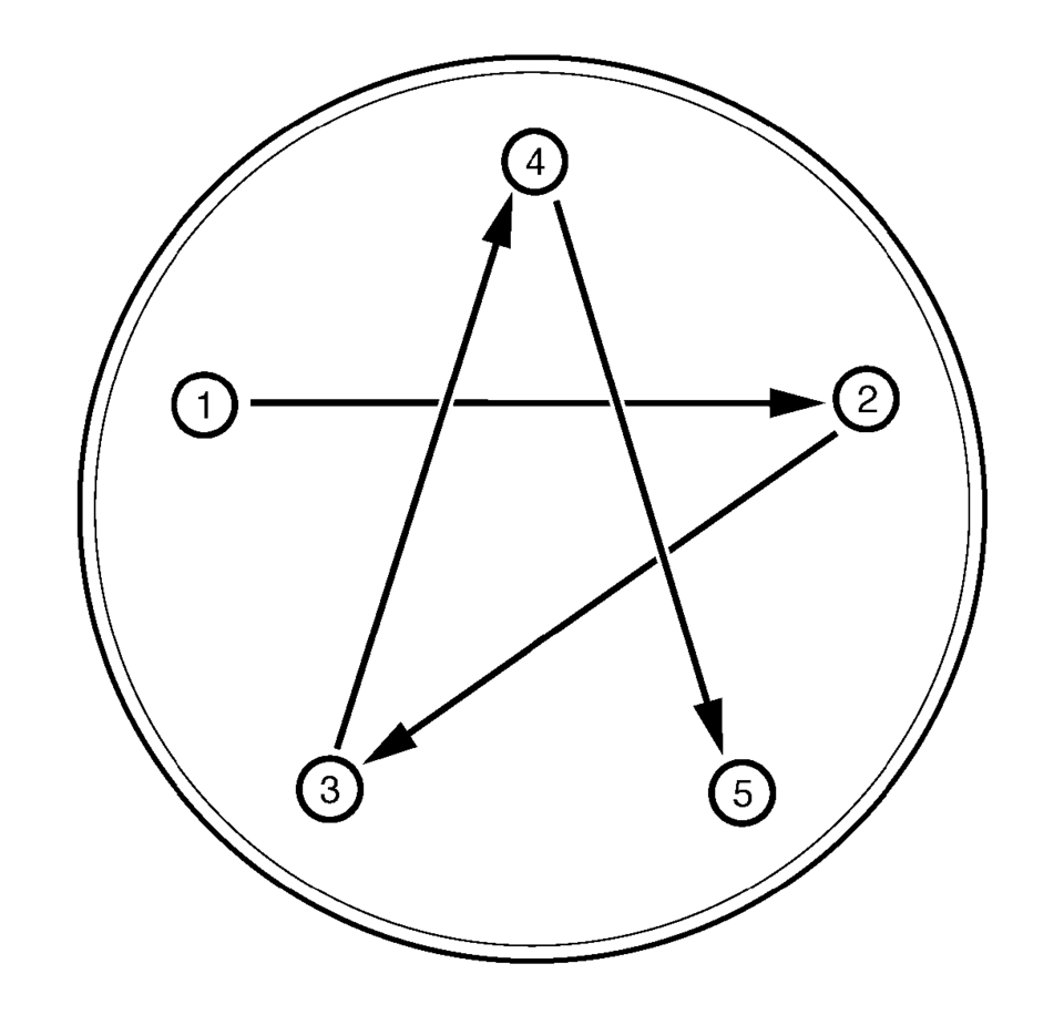
- Using a torque wrench and the appropriate socket, alternately and evenly
tighten the wheel nuts to?€‰140?€‰Y (103?€‰lb?€‰ft)
in the sequence illustrated.
- Install the wheel nut caps?€‰(1), if equipped.
- Install the wheel center cap or wheel cover, if equipped.
Warning:
Before installing the wheels, remove any buildup of corrosion on the wheel mounting surface and brake drum or disc mounting surface. Installing wheels with poor metal-to-metal contact at the mounting surfaces can cause wheel nuts to loosen. This can cause a wheel to come off when the vehicle is moving, causing loss of control and possibly personal injury.
Note:
Do not use power grinding tools to clean the brake rotor or drum to wheel mating surfaces.
Warning:
Never grease or lubricate wheel nuts, studs and mounting surfaces. Wheel nuts, studs, and mounting surfaces must be clean and dry. Tightening the lubricated parts can cause damage to the wheel studs. This can cause a wheel to come off when the vehicle is moving, causing loss of control and possibly personal injury.
Caution:
Improperly tightened wheel bolts or nuts can lead to brake pulsation and rotor damage. In order to avoid expensive brake repairs, evenly tighten the wheel bolts or nuts to the proper torque specification.
Caution:
Refer to Fastener Caution.
 Special Tools
Illustration
Tool Number/ Description
BO-125
KM-125
Torque Rod Lifter
...
 Front Fender Replacement
Front Fender Replacement
Callout
Component Name
Preliminary Procedures
Remove the front bumper fascia. Refer to Front Bumper Fascia ...
Other materials:
Tire Pressure Monitor System
The Tire Pressure Monitor System (TPMS) uses radio and sensor technology to check
tire pressure levels. The TPMS sensors monitor the air pressure in your tires and
transmit tire pressure readings to a receiver located in the vehicle.
Each tire, including the spare (if provided), should be check ...
Steering Wheel Horn Contact Replacement
Steering Wheel Horn Contact Replacement
Callout
Component Name
Preliminary Procedure
Remove the steering wheel inflatable restraint module. Refer to Airbag
Steering Wheel Module Replacement.
1
S ...
Control Solenoid Valve and Transmission Control Module Assembly Installation
Control Solenoid Valve and Transmission Control Module Assembly Installation
Callout
Component Name
1
Control Solenoid Valve Assembly Filter Plate
Caution: Use care when removing or installing the filter plate
...

0.0058