Chevrolet Sonic Repair Manual: Tire-to-Wheel Match-Mounting (Vectoring)
Note:
After remounting a tire to a wheel or after replacing a tire and/or a wheel, remeasure the tire and wheel assembly runout in order to verify that the amount of runout has been reduced and brought to within tolerances. Ensure that the tire and wheel assembly is properly balanced before reinstalling to the vehicle.
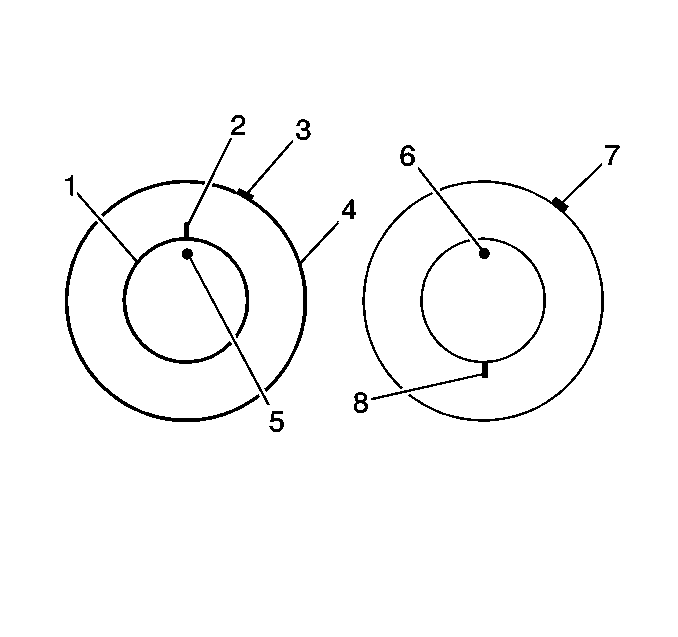
- Mark the location of the high spot (3) on the tire as determined during the off-vehicle tire and wheel assembly runout measurement.
- Place a reference mark (2) on the tire sidewall at the location of the valve stem (5).
- Always refer to the valve stem as the 12 o'clock position.
- Refer to the location of the high spot (3) by its clock position on the wheel, relative to the valve stem.
- Tire and Wheel Assembly Balancing - Off Vehicle
- Tire and Wheel Removal and Installation
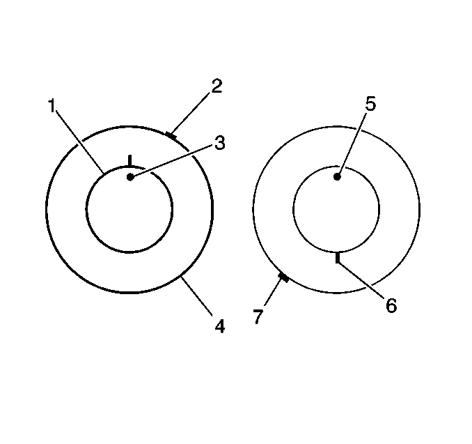
- If the clock location of the high spot (7) is now at or near a position 180 degrees from the original clock location of the high spot, the tire is the major contributor to the assembly runout concern.
- If the clock location of the high spot is now in-between the 2 extremes, then both the tire and the wheel are both contributing to the assembly runout concern. Rotate the tire an additional 90 degrees in both the clockwise and the counterclockwise directions to obtain the lowest amount of assembly runout.
 Tire and Wheel Removal and Installation
Special Tools
CH-41013 Rotor Resurfacing Kit
CH-42450-A Wheel Hub Resurfacing Kit
For equivalent regional tools, refer to Special Tools.
Removal Procedure
Ra ...
 Tires and Wheels Description and Operation
There are two types of tire and wheel balancing: static and dynamic.
Static balance is the equal distribution of weight around the wheel. Assemblies
that are statically unbalanced cause a bouncing ...
Other materials:
SIR Service Precautions
General Service Instructions
Warning: When performing service on or near the SIR components
or the SIR wiring, the SIR system must be disabled. Refer to SIR Disabling
and Enabling . Failure to observe the correct procedure could cause deployment
of the SIR components, person ...
Turbocharger Coolant Return Pipe Replacement (LUV)
Turbocharger Coolant Return Pipe Replacement
Callout
Component Name
Preliminary Procedure
Remove the turbocharger. Refer to Turbocharger Replacement.
1
Turbocharger Fastener
Caution: Refer t ...
Fuel Pressure Sensor Replacement
Fuel Pressure Sensor Replacement
Callout
Component Name
Preliminary Procedure
Relieve the fuel system pressure. Refer to
Fuel Pressure Relief.
Remove the air cleaner assembly. Refer to
Air Cleaner Assembly Replacement. ...

0.0087