Chevrolet Sonic Repair Manual: Transmission Case Disassemble (Gen 1)
Special Tools
- 3-9506289 Universal Adapter
- J-810700 Mainshaft Bearing Remover
- J-810704 Center Bar Puller
- M-680770 Universal Sliding Mallet
- R-0007758 Holding Fixture
- R-0007770 Holding Fixture Adapter Plates
- T-0307000 Extractor and Driver Fixture
- T-9807671 Slide Hammer
For equivalent regional tools, refer to Special Tools.
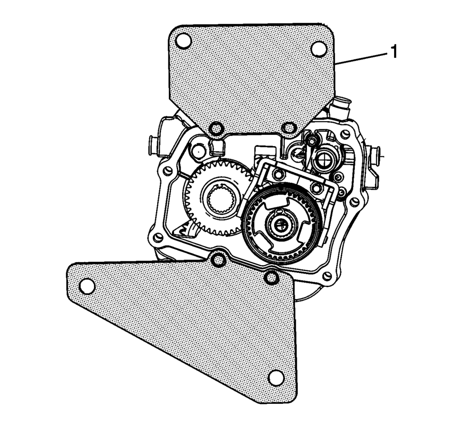
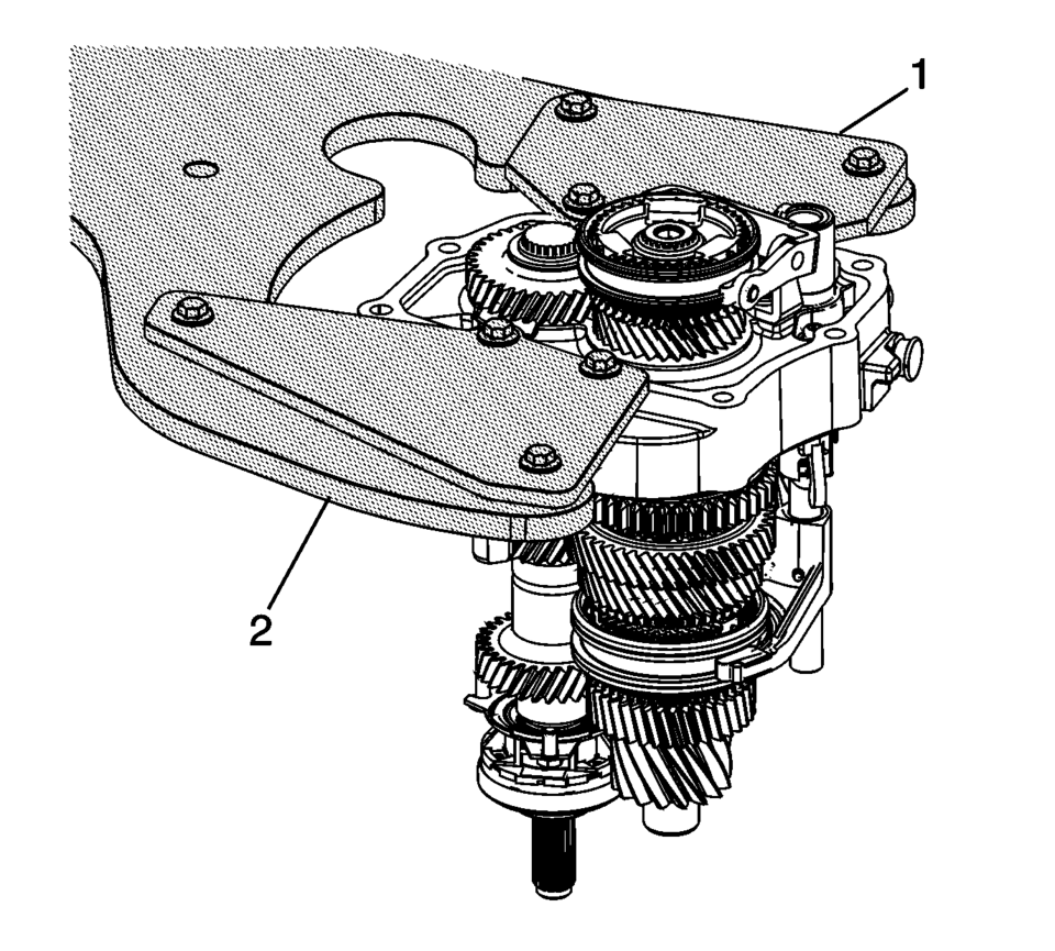
- Install both plates of the R-0007770 holding fixture adapter plates to the transmission case assembly (1).
- Install the transmission case, with the R-0007770 holding fixture adapter plates (1) to the R-0007758 holding fixture (2) and 3-9506289 universal adapter .
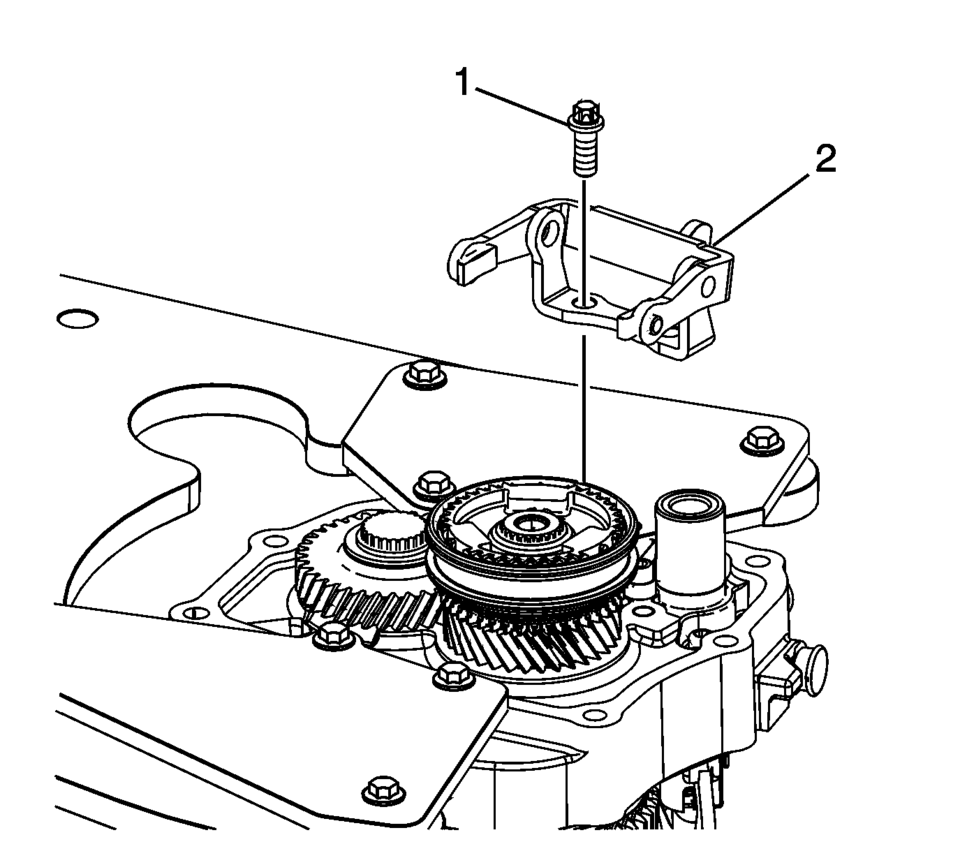
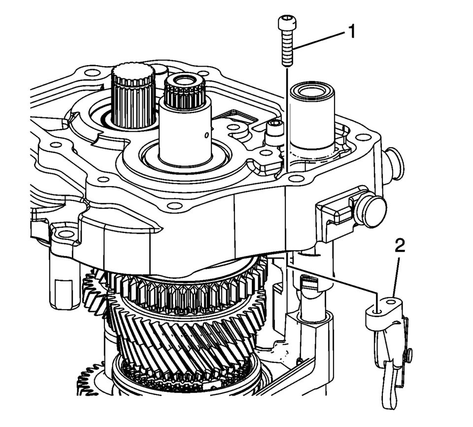
- Remove the 5th shift fork bracket retaining bolts (1).
- Remove the 5th shift fork bracket assembly (2).
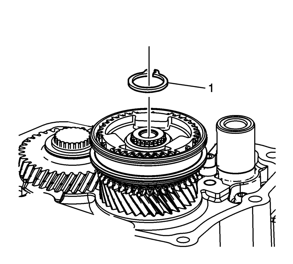
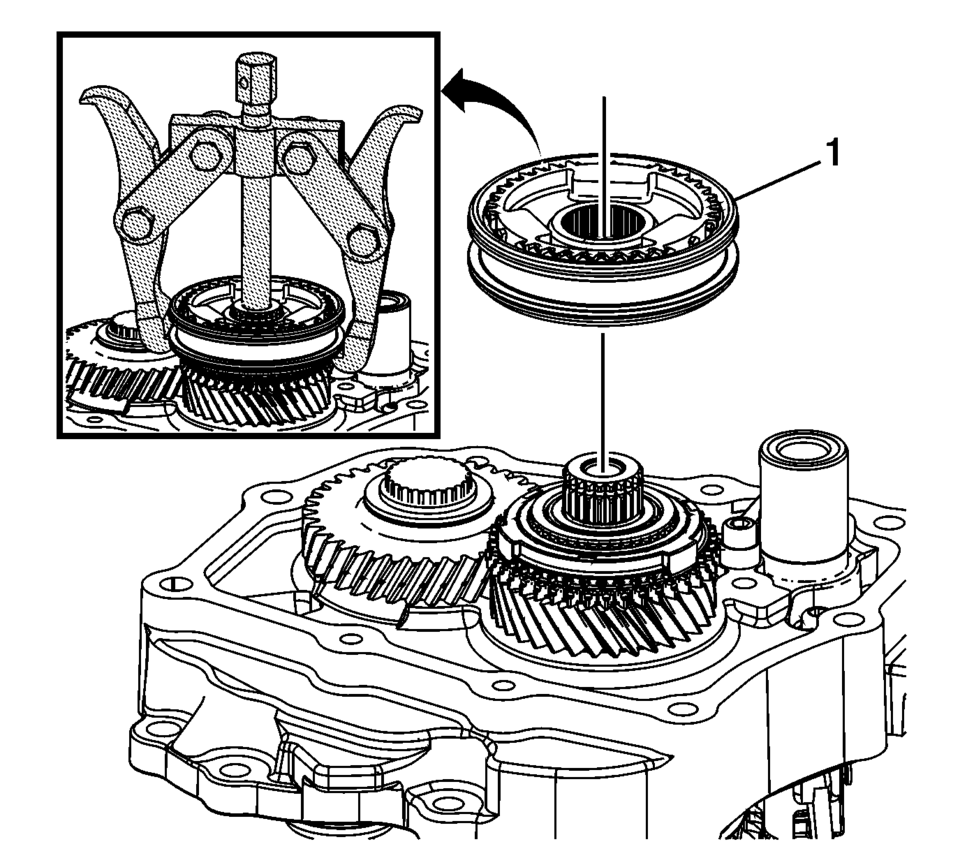
- Remove the 5th gear synchronizing hub retaining ring (1).
- Using the J-810704 puller , remove the 5th gear synchronizer assembly (1).
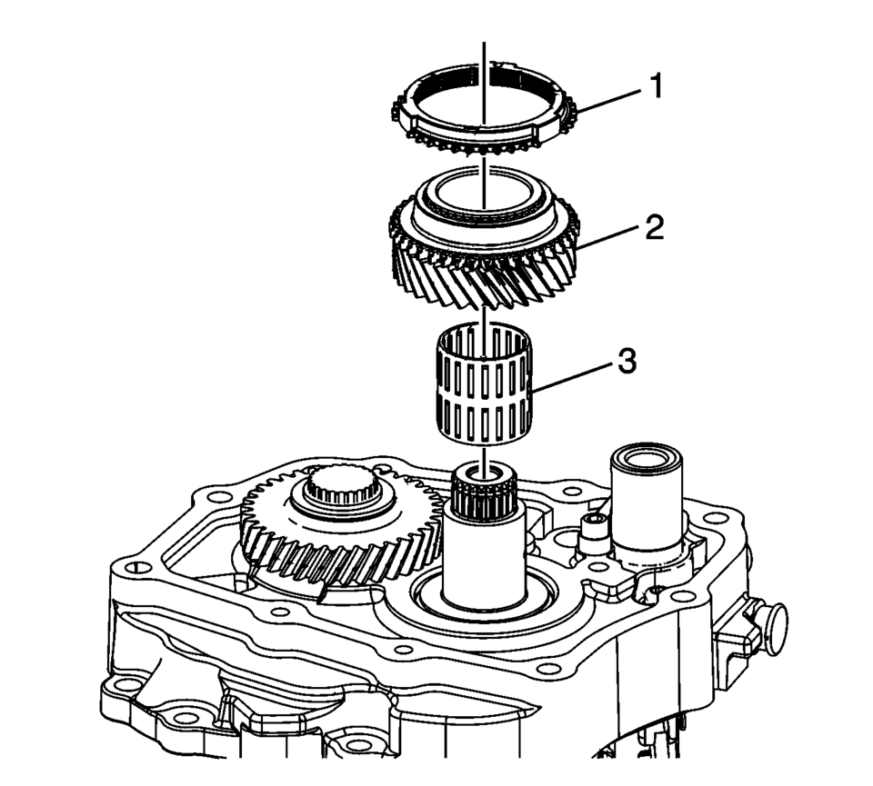
- Remove the 5th gear blocking ring (1).
- Remove the 5th gear assembly, driven (2).
- Remove the 5th gear bearing assembly (3).
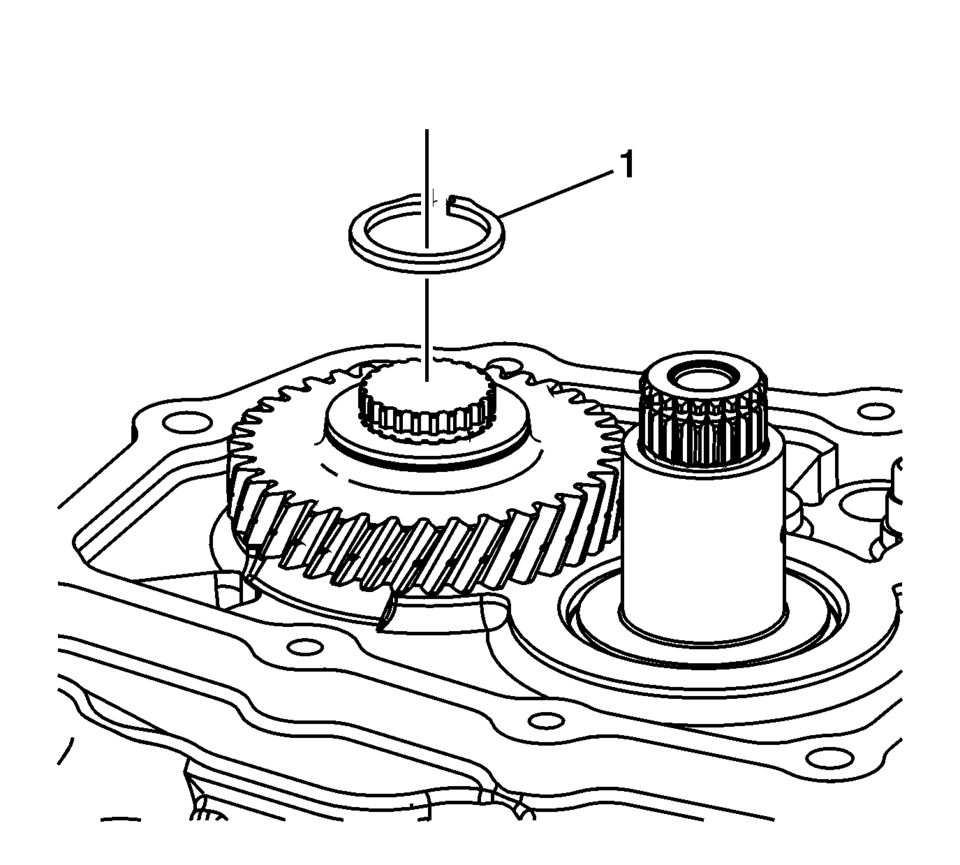
- Remove the 5th gear retaining ring (1).
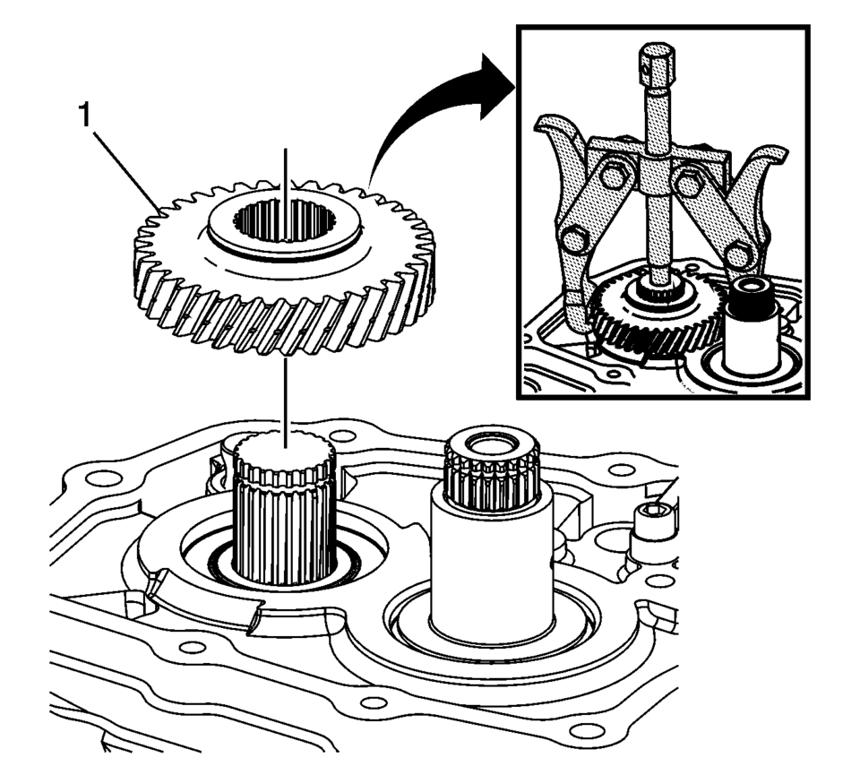
- Using the J-810704 puller , remove the 5th gear, driving (1).
- Remove the parking pawl retaining bolts (1).
- Remove the parking pawl (2).
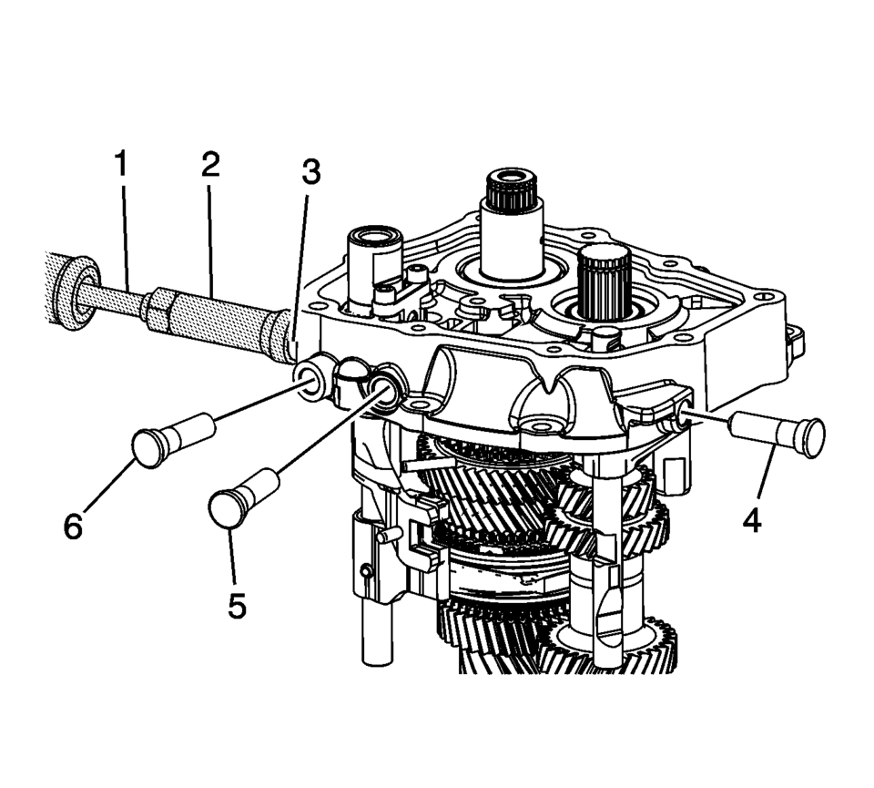
- Using the M-680770 sliding mallet adapter (2) and the T-9807671 slide hammer (1), remove the 4 shift shaft detent sleeves (3?) from the transmission case.
- The bolts are micro-encapsulated and may require that the transmission case be heated to 80?C (176?F) with a heat gun.
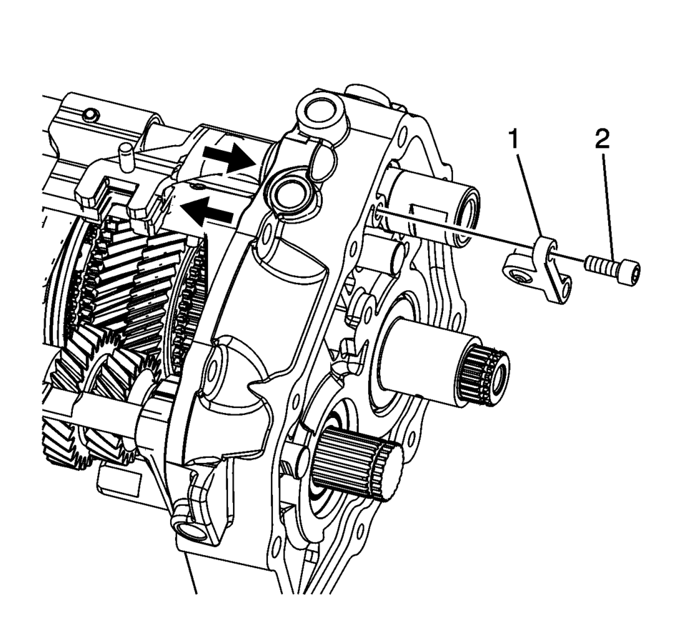
- Engage the shift shafts into 3rd gear and 5th gear as indicated with arrows to remove the interlock pin connector.
- Remove the shift shaft interlock pin connector bolts (2).
- Remove the shift shaft interlock pin connector (1).
- Remove the reverse shift fork pin (3).
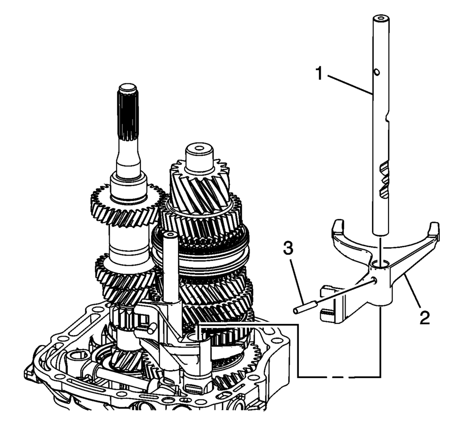
- Remove the reverse shift shaft (1).
- Remove the reverse shift fork (2).
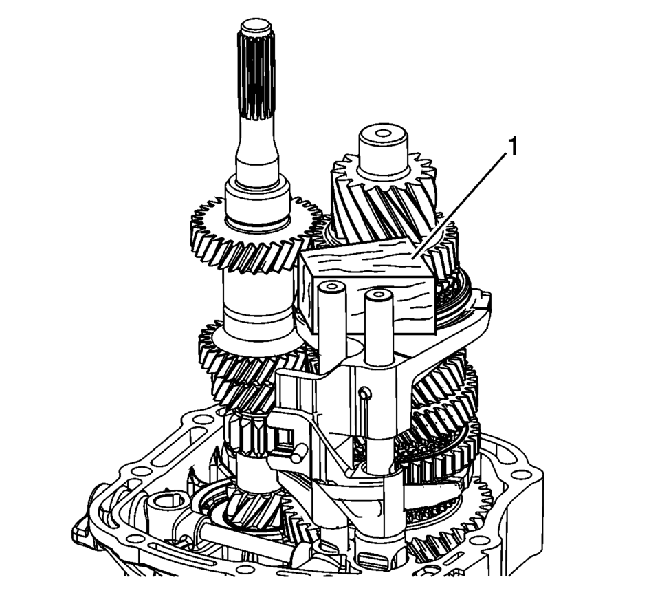
- Use a block of wood (1) to relieve the pressure on the gearshift rod guides.
- Remove the 3rd and 4th shift fork pin (3).
- Remove the 3rd and 4th shift shaft (1).
- Remove the 3rd and 4th shift fork (2).
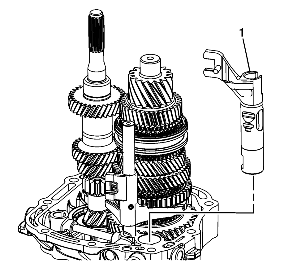
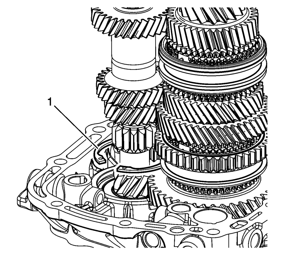
- Remove the 5th shift blocking guide (1) from the transmission case.
- Remove the gearshift rod (1) from the transmission case.
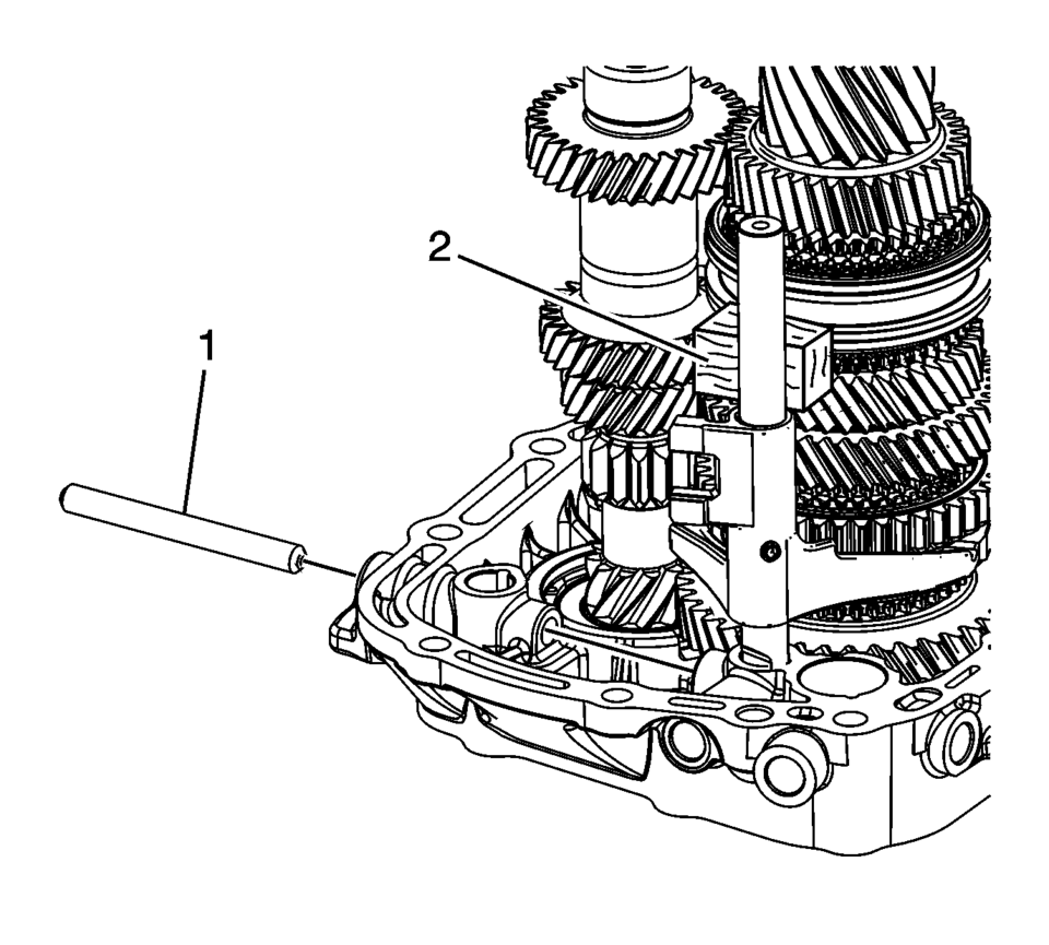
- Insert a block of wood (2) to relieve pressure on the gearshift rod guides.
- Remove the 1st and 2nd shift fork pin (3).
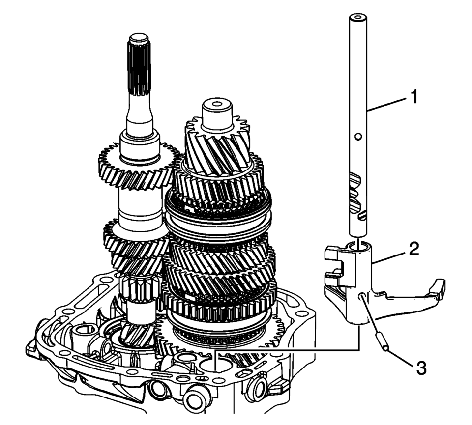
- Remove the 1st and 2nd shift shaft (1).
- Remove the 1st and 2nd shift fork (2).
- Remove the input shaft bearing retaining ring (1) from the bore, and leave it on the shaft.
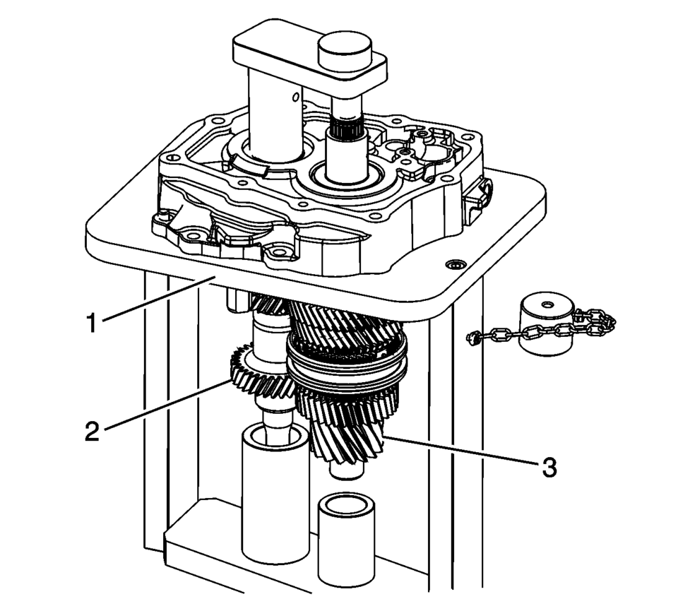
- Remove the transmission case from R-0007770 adapter plates and install onto the T-0307000 fixture .
- Support the mainshaft (3), input shaft (2) and reverse idler gear (1) while pressing the shafts from the case.
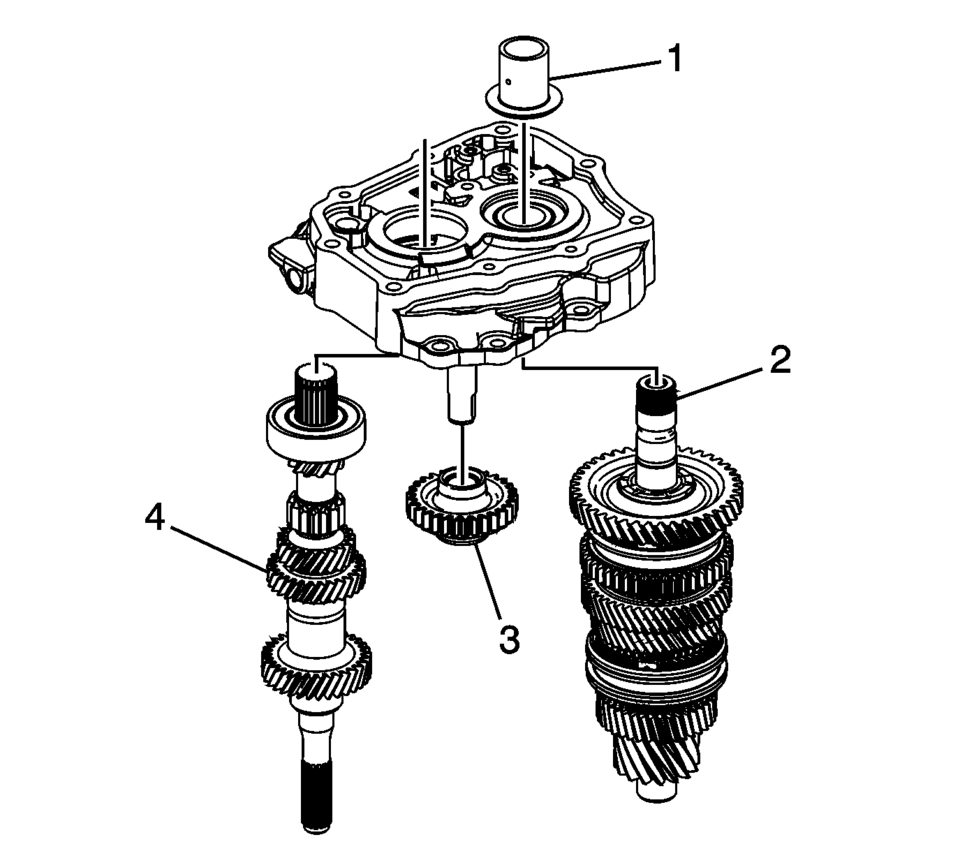
- Remove the input shaft (4), reverse idler gear (3) and mainshaft (2) from the T-0307000 fixture .
- Remove the 5th gear bearing race (1) from the transmission case.
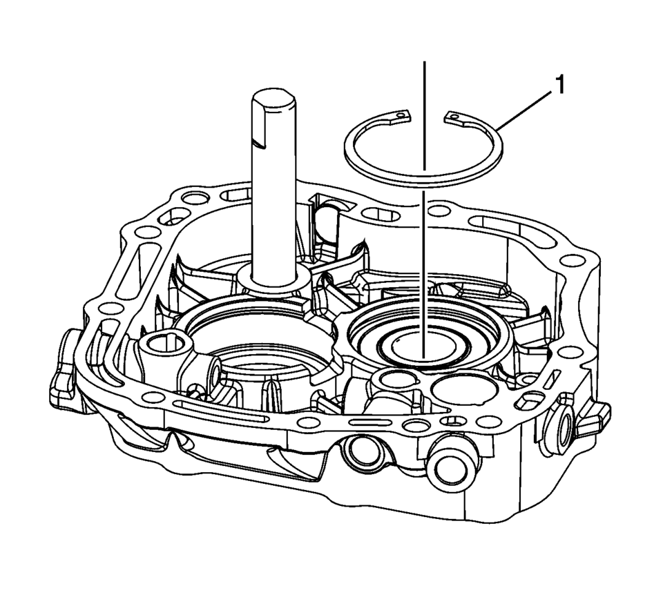
- Remove the mainshaft bearing retaining ring (1).
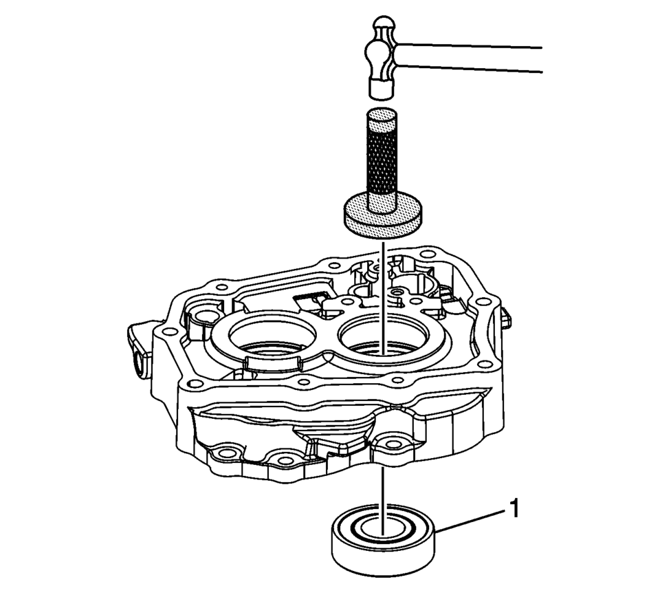
- Using J-810700 mainshaft bearing remover , remove the mainshaft bearing (1) from the case.
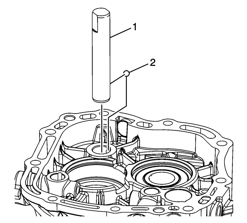
- Remove the reverse idler gear shaft (1) from the case.
- Remove the reverse idler gear shaft retaining ball (2).
Note:
The parking pawl bolts are micro-encapsulated and may require that the transmission case be heated to 80?C (176?F) with a heat gun.
Note:

Note:
Be prepared to support the reverse idler gear, input shaft and mainshaft as they are pressed from the case.
 Transmission Case Assemble (Gen 2)
Special Tools
3-9506289 Universal Adapter
J-840733 Driver
R-0007758 Holding Fixture
R-0007761 Universal Handle
R-0007770 Holding Fixture Adapter Plates
T-9804669 Seal Installer
T-0 ...
 Transmission Case Disassemble (Gen 2)
Special Tools
3-9506289 Universal Adapter
J-810700 Mainshaft Bearing Remover
J-810704 Center Bar Puller
M-680770 Universal Sliding Mallet
R-0007758 Holding Fixture
R-0007770 Holding F ...
Other materials:
Seat Adjustment
Manual Seats
Warning: You can lose control of the vehicle if you try to adjust
a driver seat while the vehicle is moving. Adjust the driver seat only when
the vehicle is not moving.
To adjust a manual seat:
Pull the handle at the front of the seat.
Slide the ...
Air Conditioning Compressor Bracket Installation
Install the air conditioning compressor bracket (2).
Caution: Refer to Fastener Caution.
Install the 3 air conditioning compressor bracket bolts (1) and tighten
to 22 Y (16 lb ft).
...
Low and Reverse Clutch Assembly and Low and Reverse Clutch Plate Installation
Low and Reverse Clutch Assembly and Low and Reverse Clutch Plate Installation
Callout
Component Name
1
Low and Reverse Clutch Assembly (OWC)
Note:
The Low and Reverse Clutch Assembly should rotat ...

0.0057