Chevrolet Sonic Repair Manual: Transmission Case Assemble (Gen 2)
Special Tools
- 3-9506289 Universal Adapter
- J-840733 Driver
- R-0007758 Holding Fixture
- R-0007761 Universal Handle
- R-0007770 Holding Fixture Adapter Plates
- T-9804669 Seal Installer
- T-0307000 Extractor and Driver Fixture
For equivalent regional tools, refer to Special Tools.
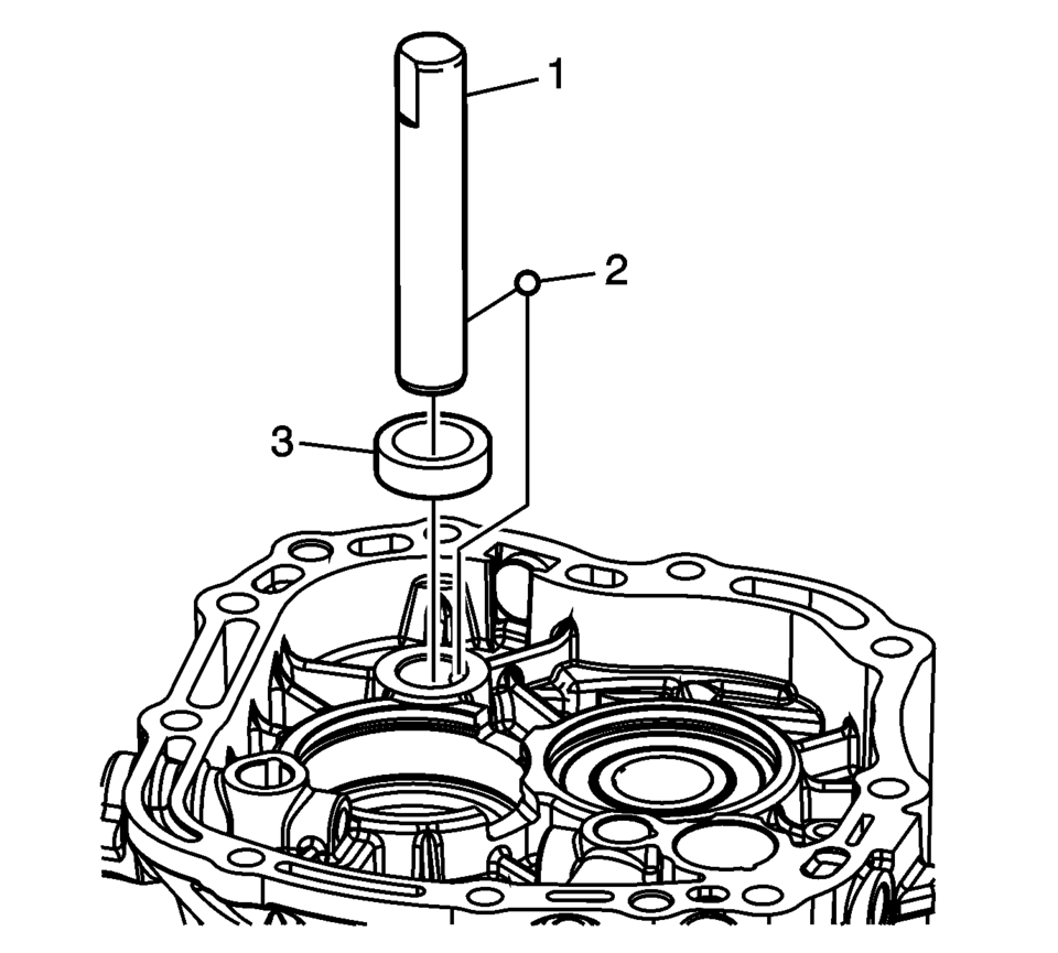
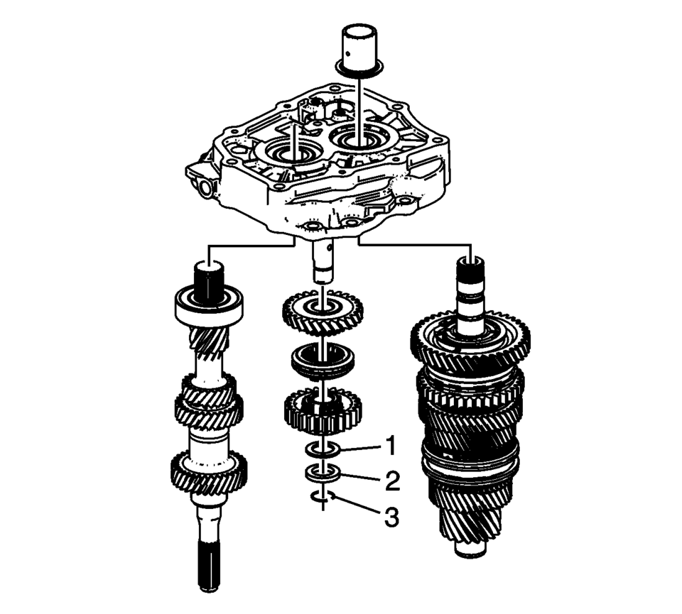
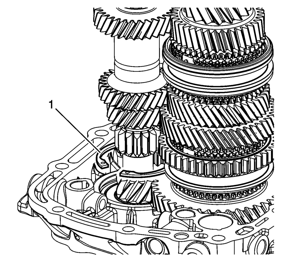
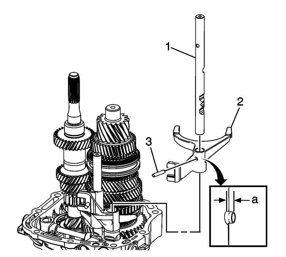
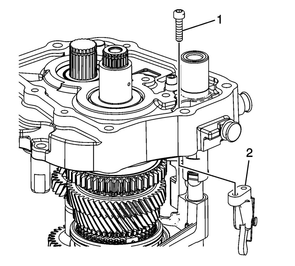
- Install the reverse helical gear washer (3) onto the reverse idler gear shaft.
- Install the reverse idler gear shaft retaining ball (2).
- Install the reverse idler gear shaft (1).
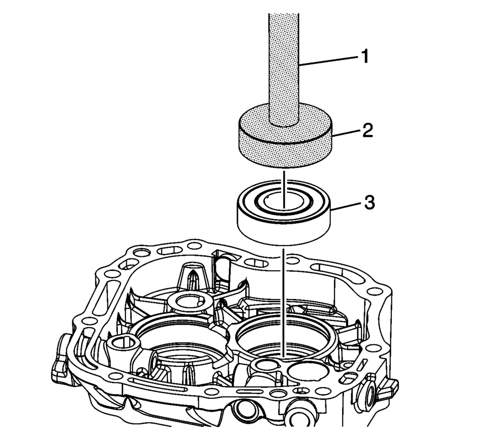
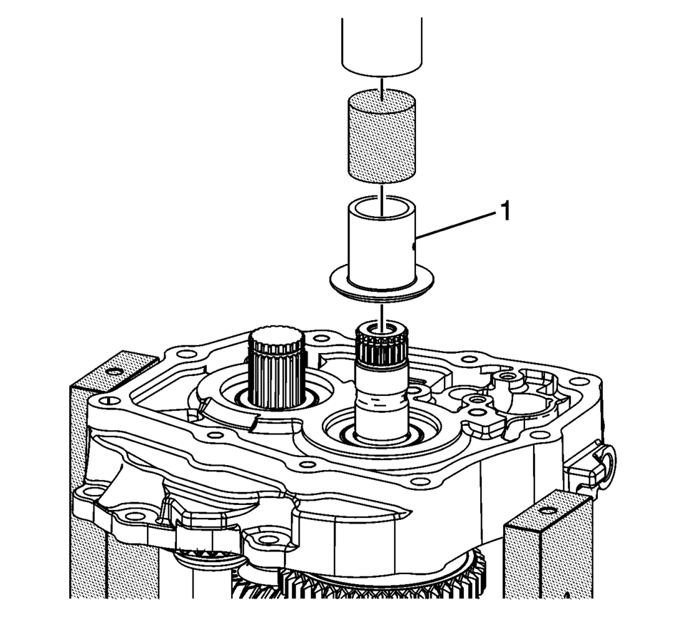
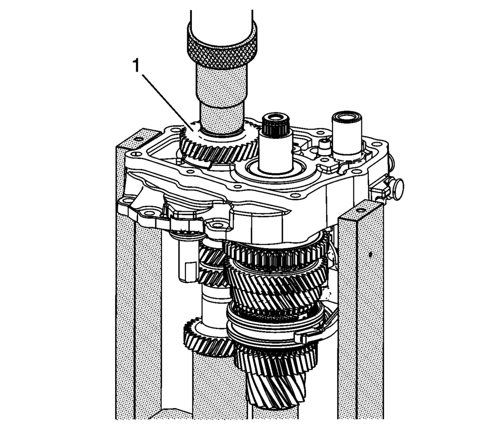
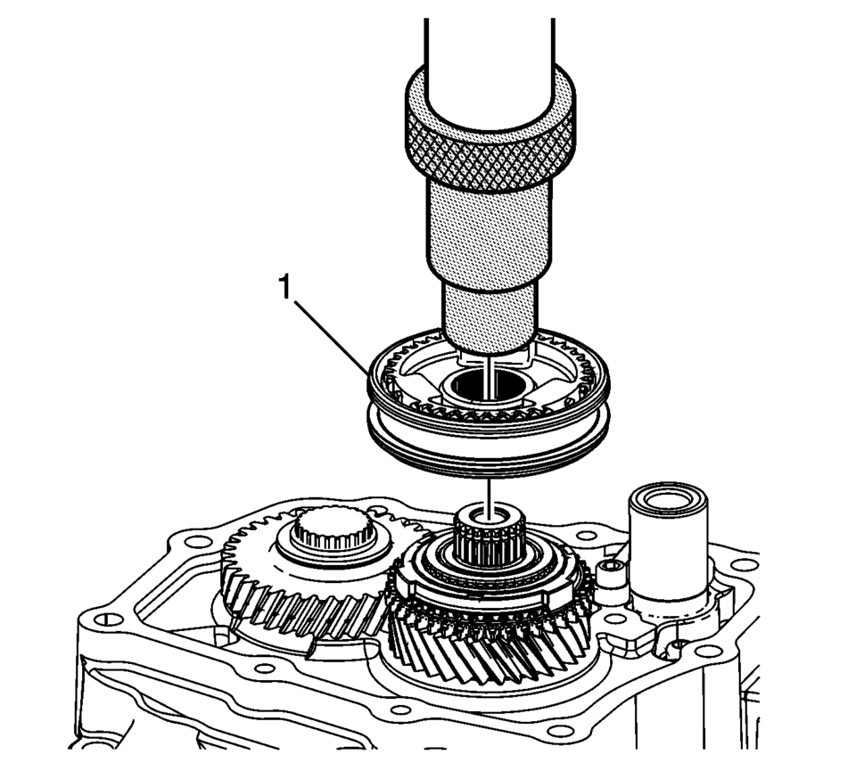
- Using T-9804669 seal installer (2) and R-0007761 handle (1), install the mainshaft bearing (3) into the case.
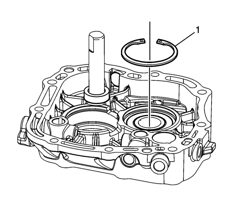
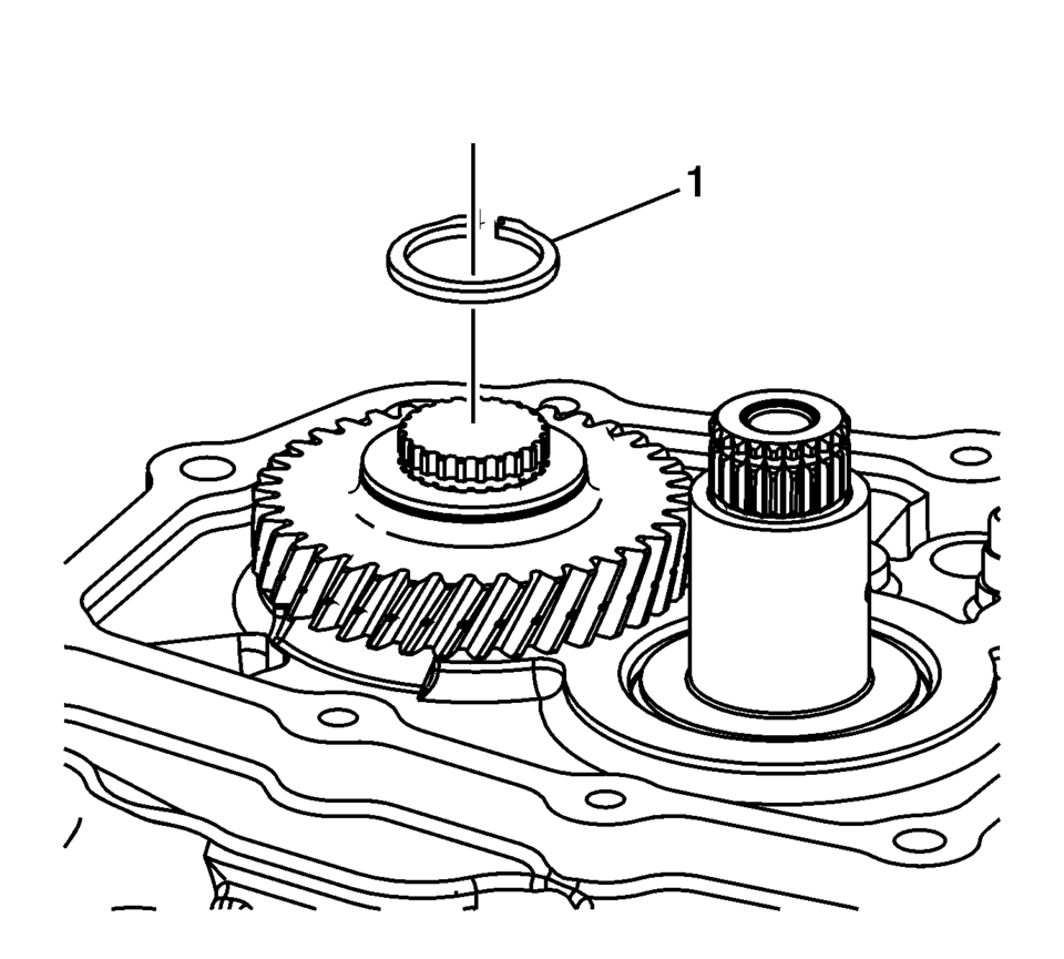
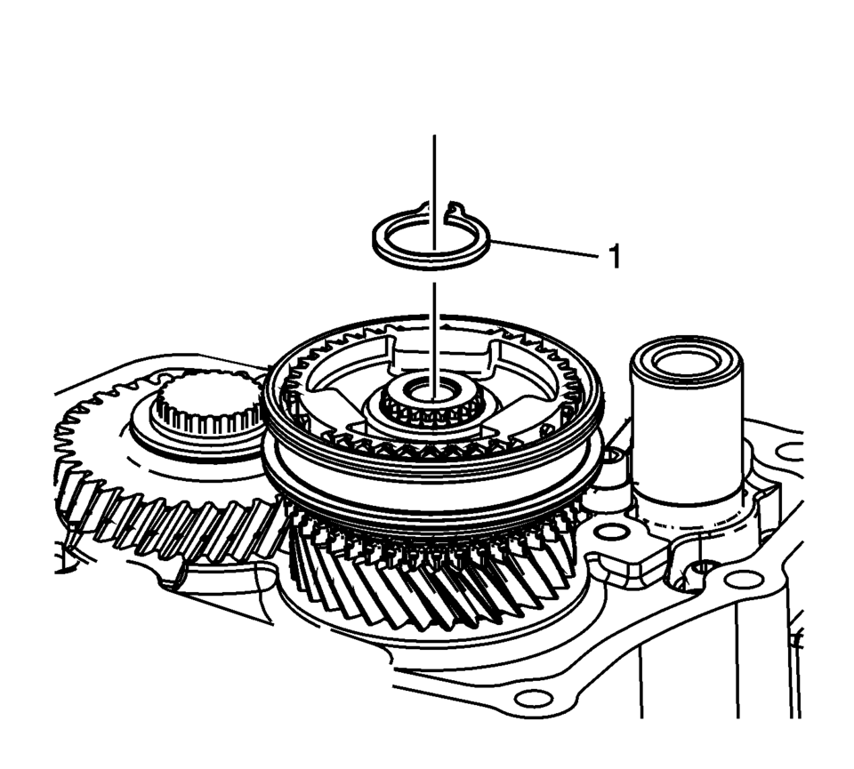
- Install the mainshaft bearing retaining ring (1).
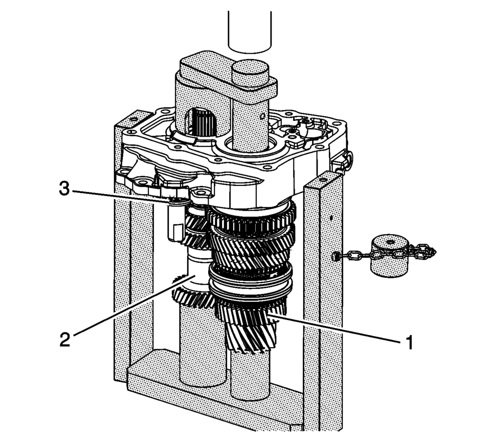
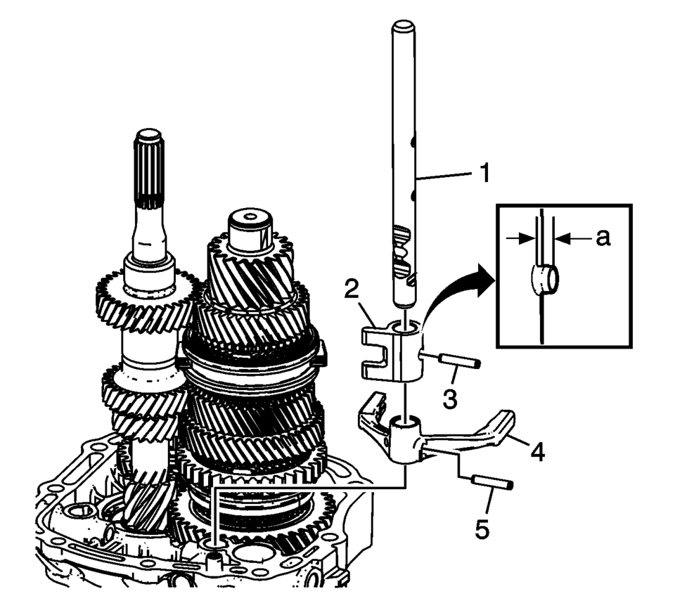
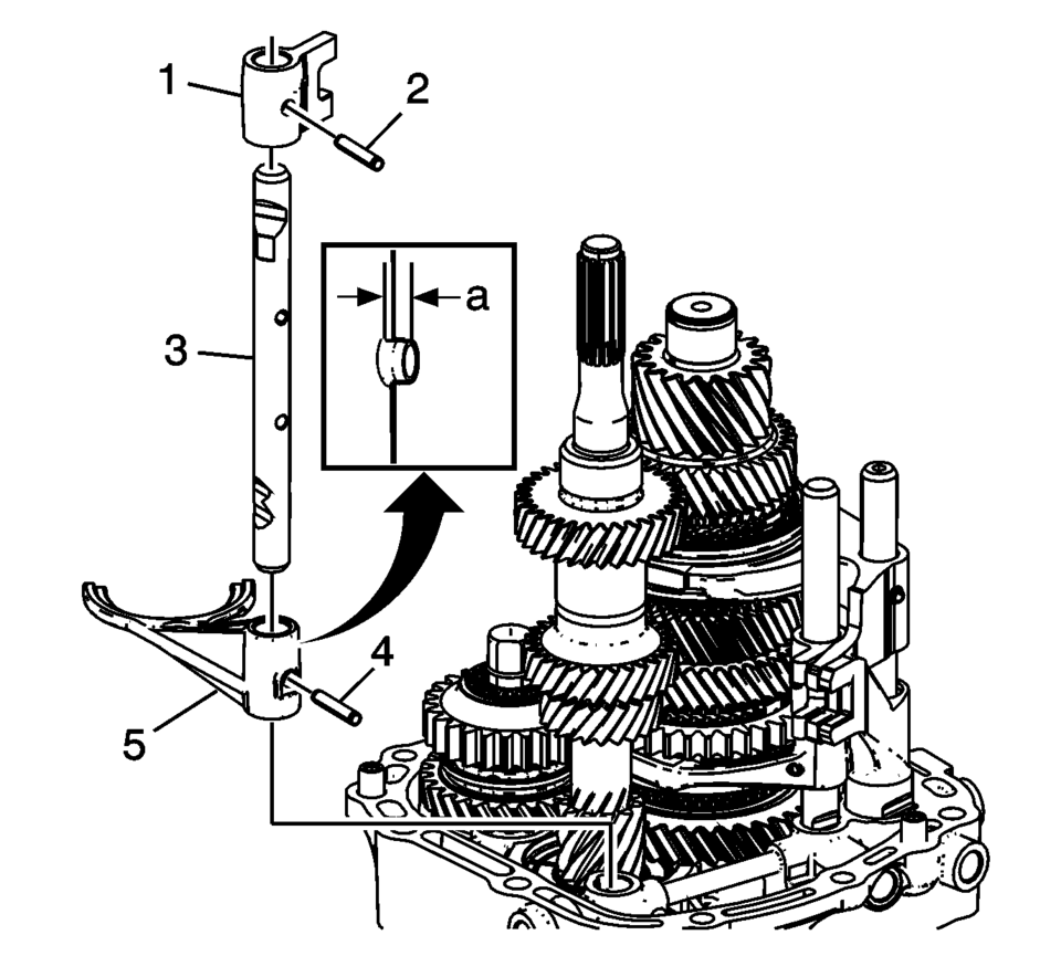
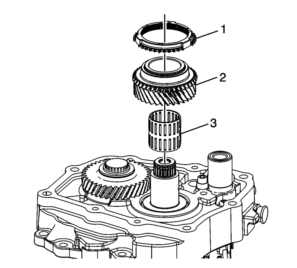
- Install the following components onto the T-0307000 driver fixture with top plate removed.
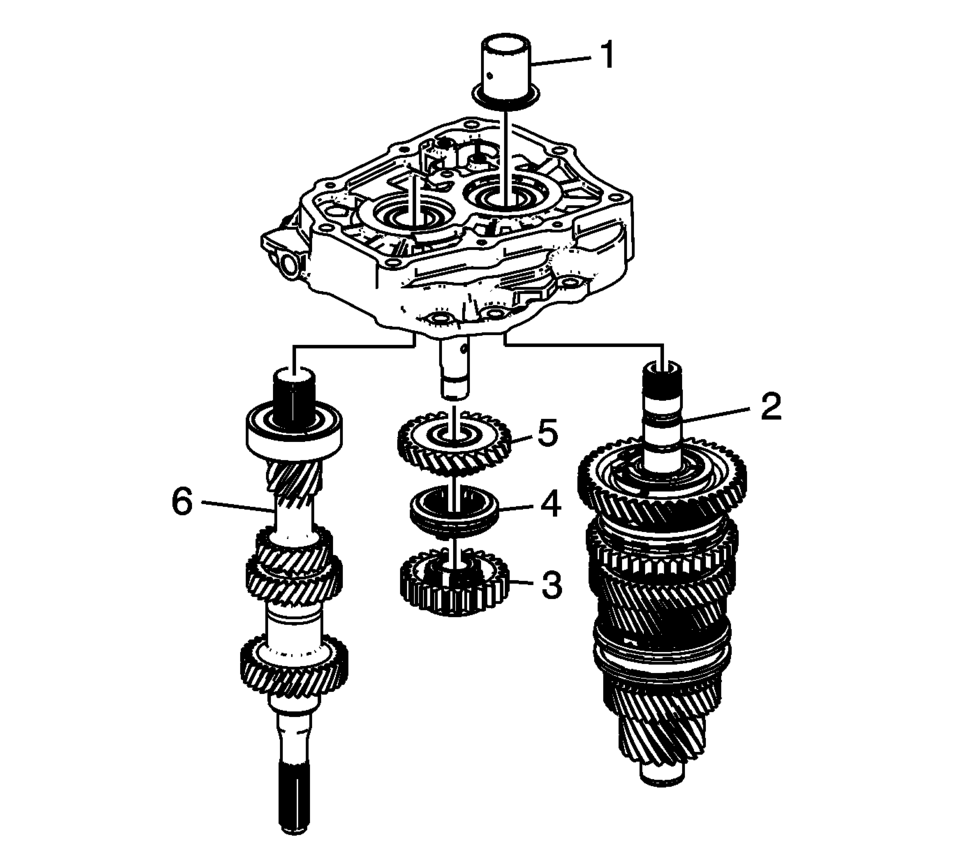
- Main shaft (2)
- Reverse helical gear (5)
- Reverse synchro assembly (4)
- Reverse spur gear (3)
- Input Shaft (6)
Note:
While pressing, pay attention to the input shaft bearing retaining ring, because it can be pressed into the first gear.
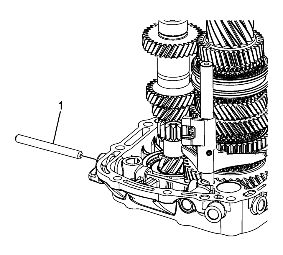
Note:
The reverse gear shaft snap ring (3) MUST be installed even if not originally equipped to prevent shifting issues caused by incorrect assembly or parts not in position.
.
.
.
.
.
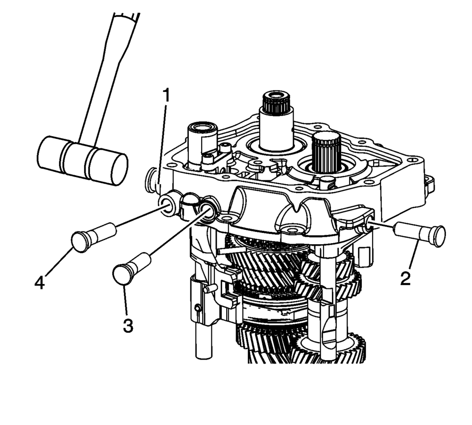
Note:
Engage the shift shafts into 2nd gear, 5th gear, and 3rd gear as indicated with arrows to install the interlock pin connector.
.
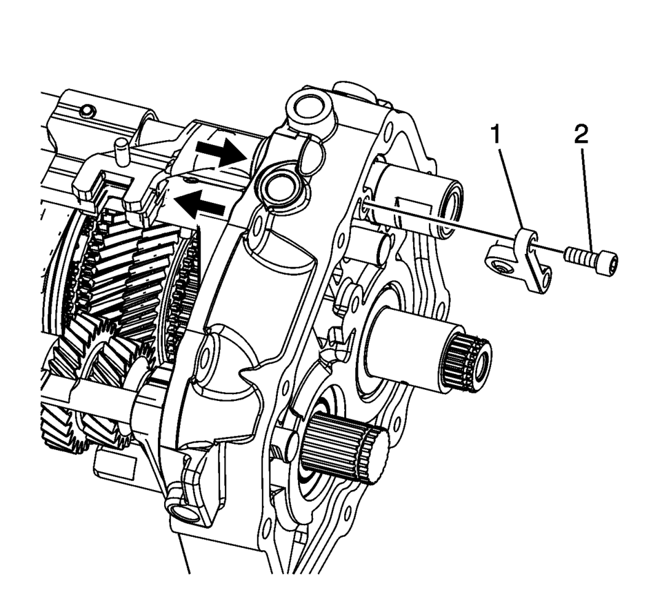
Note:
Move shift forks into neutral position.
Caution:
Refer to Fastener Caution.
.
.
 Transmission Case Assemble (Gen 1)
Special Tools
3-9506289 Universal Adapter
J-840733 Driver
R-0007758 Holding Fixture
R-0007761 Universal Handle
R-0007770 Holding Fixture Adapter Plates
T-9804669 Seal Installer
T-0 ...
 Transmission Case Disassemble (Gen 1)
Special Tools
3-9506289 Universal Adapter
J-810700 Mainshaft Bearing Remover
J-810704 Center Bar Puller
M-680770 Universal Sliding Mallet
R-0007758 Holding Fixture
R-0007770 Holding F ...
Other materials:
Tires and Wheels Description and Operation (Tire Identification)
Identification
Accessory and warranty replacement must use TPC spec tires.
An outboard orientation stripe is added to the tread surface, with an
offset toward the outboard tire face.
All GM approved tires (Production, Service and Accessory) have a TPC
(Tire Performance C ...
Fuel Tank Fuel Pump Module Replacement (Steel Tank)
Special Tools
EN-48279 Fuel Sender Lock Ring Wrench
For equivalent regional tools, refer to Special Tools.
Removal Procedure
Relieve the fuel system pressure. Refer to Fuel Pressure Relief.
Remove the fuel tank. Refer to Fuel Tank Replacement.
Disconnect the ...
Differential lock mode switch
The rear differential lock (DIFF-LOCK) in the Nissan Armada is designed to evenly
distribute engine torque between the left and right rear wheels, improving traction
in low-grip conditions.
To activate the differential lock in the Nissan Armada, reduce speed below 4
MPH (7 km/h), switch t ...

0.0068