Chevrolet Sonic Repair Manual: Valve Stem Oil Seal and Valve Spring Replacement
Special Tools
- 207649 Rod Hairpin Clips
- 547324 Flange Screws
- EN-840 Pliers / Remover
- EN-958 Installer
- EN-45059 Angle Meter
- EN-50717 Kit
- J-43649?E Rods
For equivalent regional tools, refer to Special Tools.
- Removal Procedure
-
- Remove the spark plugs. Refer to Spark Plug Replacement.
- Remove the camshaft position actuator. Refer to Camshaft Sprocket Replacement.
- Remove both camshafts. Refer to Camshaft Replacement.
- Remove the valve lifter. Refer to Valve Lifter Replacement.
- For cylinder 1 and 4 set the crankshaft to TDC marking, cylinder number 1. Use the crankshaft balancer bolt.
- For cylinder 2 and 3, set the crankshaft BDC (180 degrees from TDC marking). Use the crankshaft balancer bolt.
- Shift to 1. gear (MT) or park position (AT) and apply the park brake.

Note:
Wheels must contact the ground.
- Valve Stem Oil Seal Removal
-
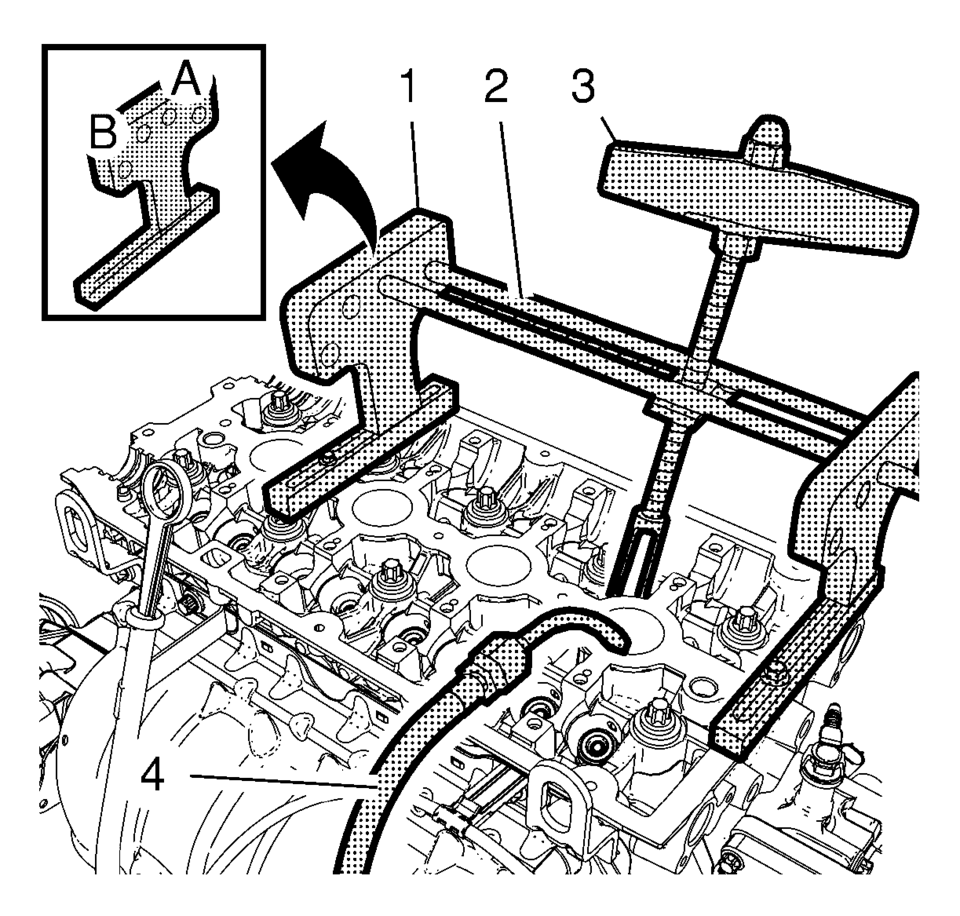
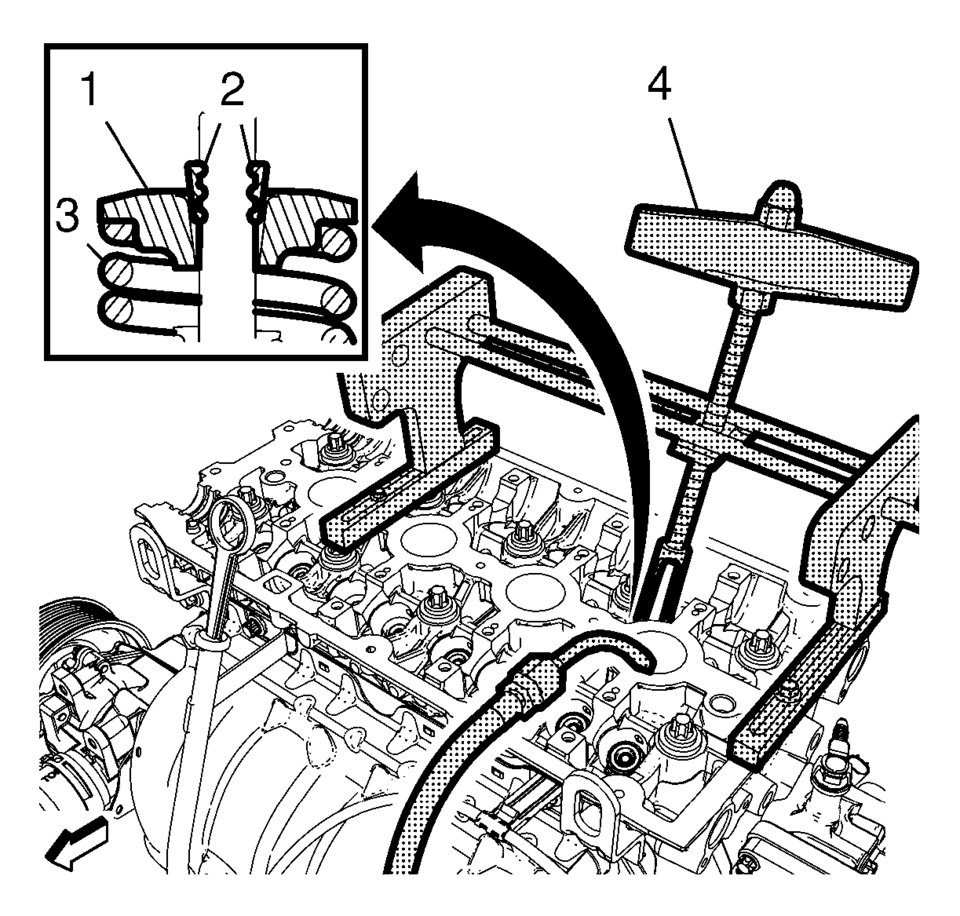
- Install the 2 EN-50717?E stands (1) to the cylinder head and fix them with the 547324 screws.
- Install the 2 J-43649-2 rods (2) and the EN-51717?E compressor (3) to the B-side of the EN-50717?E stands. Secure the rods with the 207649 clips then.
- Install an suitable air pressure adapter (4) to the spark plug hole.
- Apply air pressure to the corresponding cylinder.
- Position the EN-51717?E compressor (3) so that its adapter proper contacts the valve spring retainer and pretension the compressor.
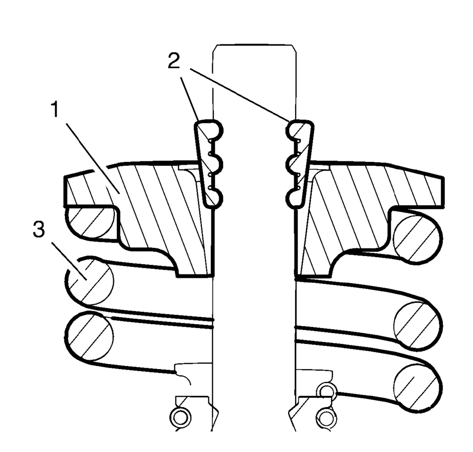
- Apply pressure to the EN-50717?E compressor to push down the vale spring retainer (1) and compress the valve spring (3) until the valve keys (2) are free from tension. Carefully remove the valve keys then.
- Release the tension from the EN-50717?E compressor.
- Remove the valve spring retainer (1) and the valve spring (3).
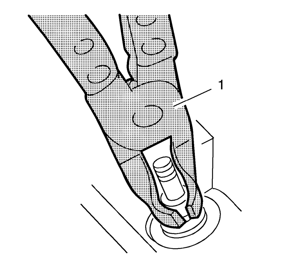
- Remove and DISCARD the valve stem oil seal, using the EN-840 pliers (1).
Warning:
Valve springs can be tightly compressed. Use care when removing the retainers and plugs. Personal injury could result.
- Valve Stem Oil Seal Installation
-
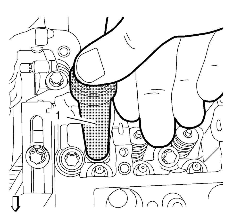
- Install the NEW valve stem oil seal, using the EN-958 installer (1).
- Loosely install the valve spring and the valve spring retainer.
- Using the EN-51717?E compressor (4), push down the valve spring retainer (1) and compress the valve spring (3) until the valve keys (2) can be inserted. Carefully insert the valve keys then, so that they are proper installed to the valve stem grooves.
- Carefully release the tension from the EN-50717?E compressor.
- Inspect the valve keys and valve spring retainer for proper seat.
- Repeat the procedure with the remaining valves and cylinders. Transfer the EN-50717?E stands and the EN-51717?E compressor as needed.
- Take care that air pressure is always applied to the combustion chamber of the treated cylinder.
Note:
Lubricate the NEW valve stem oil seal with clean engine oil.
Caution:
The valve stem keys must correctly seat in the valve spring cap. Engine damage may occur by not installing properly.
- Installation Procedure
-
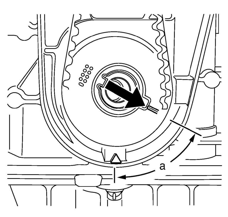
- Set the crankshaft in direction of engine rotation to 60 degrees
(a) before TDC. Use the EN-45059 meter and the crankshaft balancer bolt.
- Install the valve lifter. Refer to Valve Lifter Replacement.
- Install both camshafts. Refer to Camshaft Replacement.
- Install the camshaft position actuator. Refer to Camshaft Sprocket Replacement.
- Install the spark plugs. Refer to Spark Plug Replacement.
- Set the crankshaft in direction of engine rotation to 60 degrees

 Hydraulic Valve Lash Adjuster Arm Installation
Note: Hydraulic valve lash adjuster arms should be installed in
their original position.
Lubricate the hydraulic valve lash adjuster arms with engine oil.
Install the 16̴ ...
Other materials:
Interior Lighting
Dome Lamps
The dome lamp controls are in the headliner above the rear seats.
: Press to turn the lamps off, even
when a door is open.
: When the button is returned to
the middle position, the lamps turn on automatically when a door is opened.
: Press to turn on the dome lamps.
Reading ...
Airbag Steering Wheel Module Replacement
Removal Procedure
Warning: Refer to SIR Inflator Module Handling and Storage
Warning.
Warning: Refer to SIR Warning.
Disable the SIR system. Refer to SIR Disabling and Enabling.
Rotate the steering wheel 180 degrees.
Using a bl ...
Control Valve Channel Plate Cleaning and Inspection (6T30/40/45/50 - Gen 2)
34
Control Valve Channel Plate Cleaning and Inspection
Callout
Component Name
1
Control Valve Body Spacer Plate Retainer
2
Channel Plate to Valve Body Spacer Plate Assembly
3
...

0.0061