Chevrolet Sonic Repair Manual: Crankshaft Balancer Replacement
Special Tools
- EN-470–B Angular Torque Wrench
- EN-49979 Crankshaft Shock Mount Retainer
For equivalent regional tools, refer to Special Tools.
- Removal Procedure
-
- Raise and support the vehicle. Refer to Lifting and Jacking the Vehicle.
- Remove front wheelhouse liner extension right side. Refer to Front Wheelhouse Liner Inner Front Extension Replacement.
- Remove the drive belt. Refer to Drive Belt Replacement.
- Place collecting basin underneath.
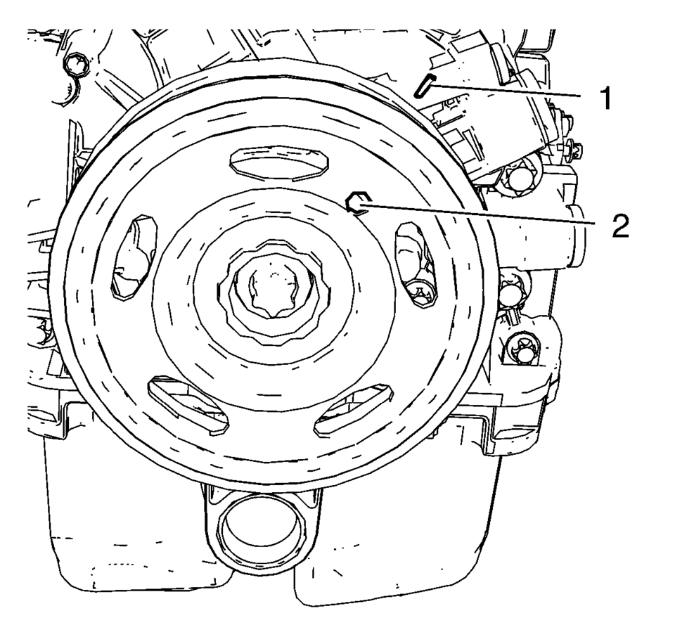
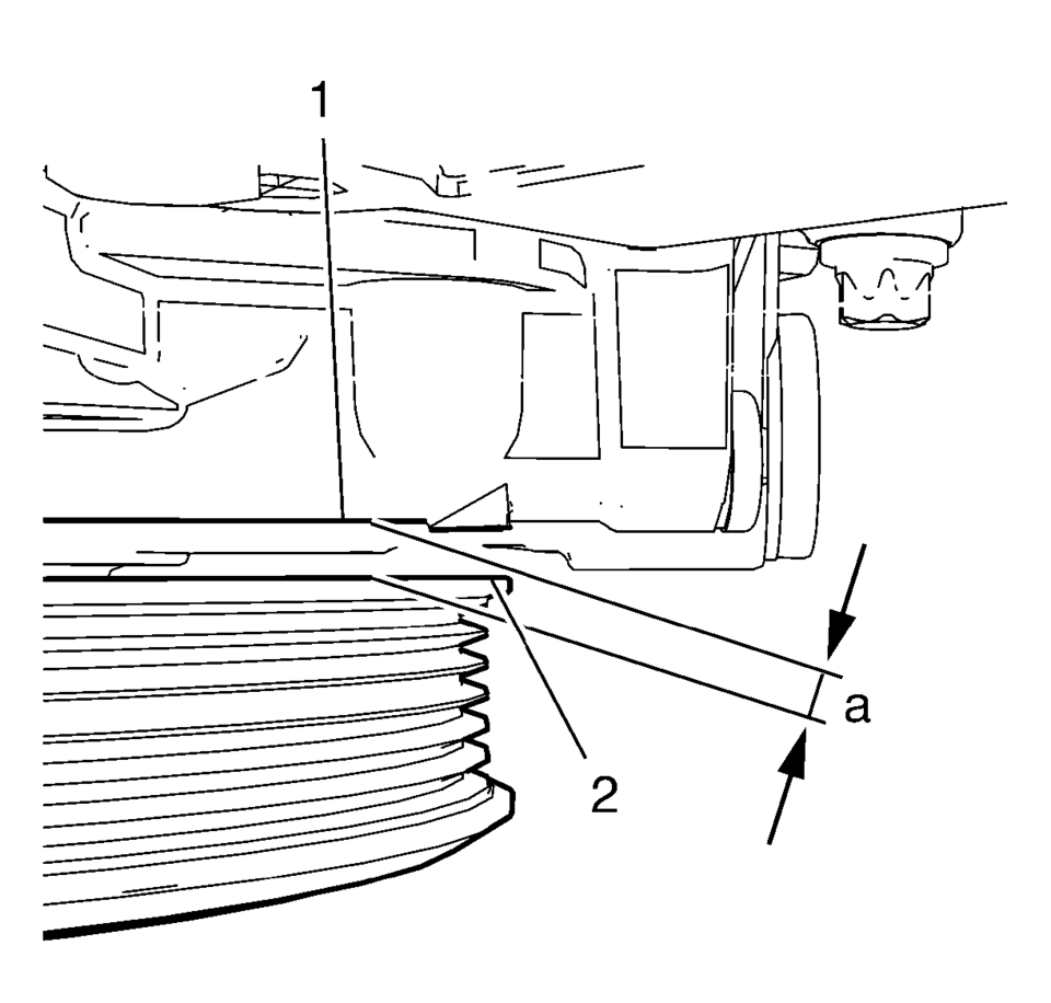
- Rotate the engine clockwise until the bore (2) in the crankshaft balancer aligns with the mark (1) on the engine front cover.
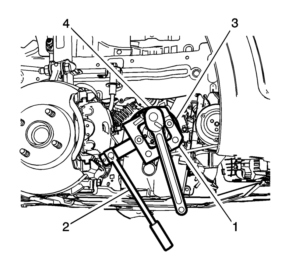
- Install EN-49979 crankshaft shock mount retainer (1) to suitable tool (2).
- Loosen the crankshaft balancer bolt (4) while holding the crankshaft balancer (3).
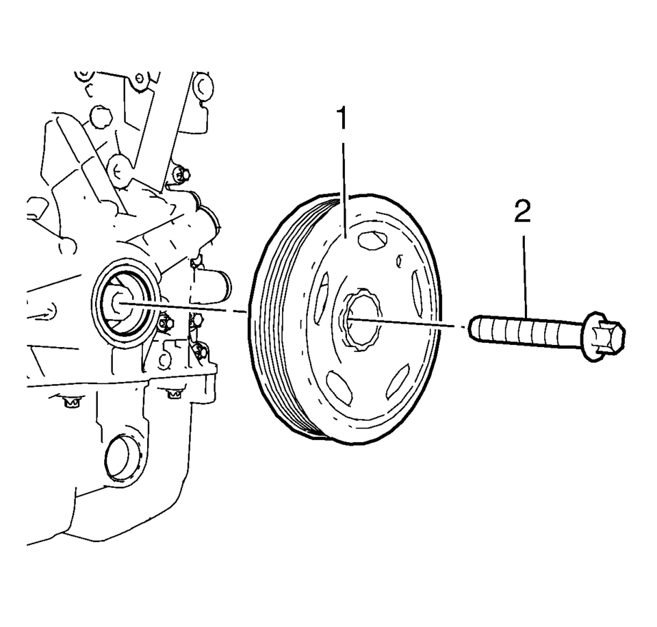
- Remove and DISCARD the crankshaft balancer bolt (2).
- Remove the crankshaft balancer (1).
Note:
The crankshaft balancer can be incorrectly installed 180° from the required position. Be sure to note the location of the alignment hole on the crankshaft balancer prior to removing the crankshaft balancer from the engine.
- Installation Procedure
-
- Install the crankshaft balancer carefully by pressing into position.
- Measure the distance (a) between the crankshaft balancer (2) and the
mark on the engine front cover (1). The distance (a) should be 5.5 mm (0.21654 in)
.
- Install a NEW crankshaft balancer bolt.
- Tighten the crankshaft balancer bolt (4) to 150 N•m (111 lb ft) while holding the crankshaft balancer (3) with EN-49979 crankshaft shock mount retainer (1) and suitable tool (2). Use EN-470-B wrench .
- Tighten the crankshaft balancer bolt to an additional 60°
.
- Install the drive belt. Refer to Drive Belt Replacement.
- Install the front wheelhouse liner extension right side. Refer to Front Wheelhouse Liner Inner Front Extension Replacement.
- Lower the vehicle.
- Check and correct engine oil level.
Note:
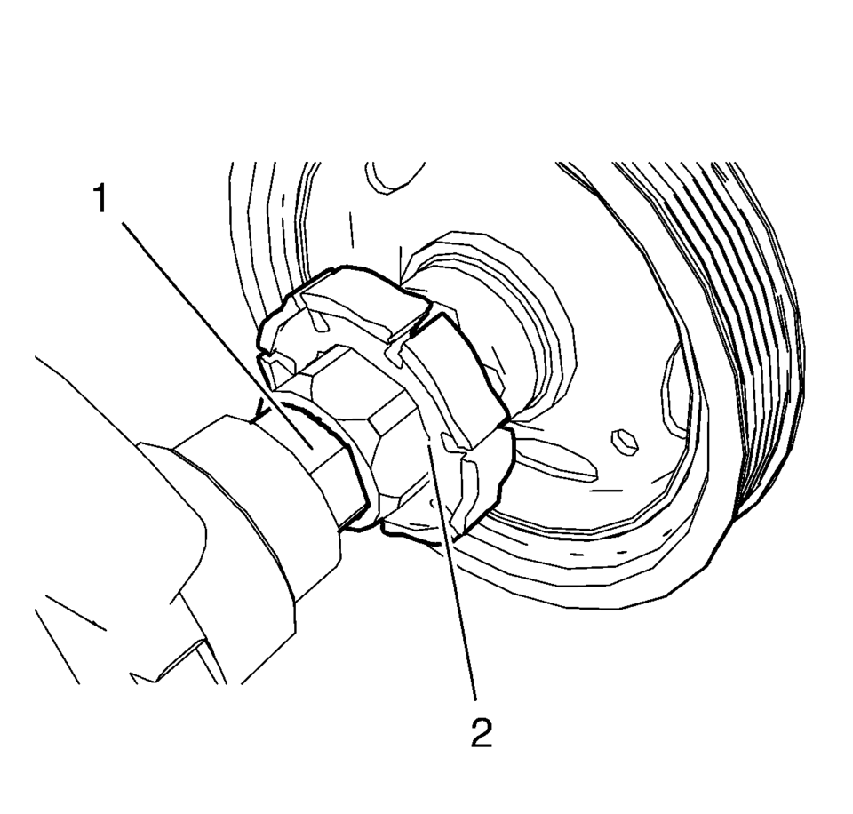
The crankshaft balancer flange must fit to the hexagon of the oil pump rotor (2) and to the two-flats of the crankshaft (1). The TDC markings on crankshaft balancer and engine front cover must match.
Note:
Never re-use the crankshaft balancer bolt.
Caution:
Refer to Fastener Caution.
Caution:
Refer to Torque-to-Yield Fastener Caution.
 Crankshaft Balancer Removal
Special Tools
EN-652 Flywheel Holder
For equivalent regional tools, refer to Special Tools.
Install the EN-652 holder (1). Lock the flywheel (2) or the automatic
transmis ...
 Crankshaft Position System Variation Learn
Note: The crankshaft position sensor system variation learn procedure
is required when the following service procedures have been performed, regardless
of whether DTC P0315 is set:
...
Other materials:
Crankshaft Front Oil Seal Installation
Special Tools
EN-6351 Mounting Sleeves
For equivalent regional tools, refer to Special Tools.
Clean the sealing surfaces.
Slide the EN-6351 sleeves (2) protective sleeve onto the crankshaft
journal.
Slide the crankshaft front oil seal (1) over the protective sleev ...
Range Selector Lever Cable Replacement
Removal Procedure
Set the park brake and chock the wheels.
Disconnect the transmission range selector lever cable
terminal (1) from the transmission manual shift lever pin.
Press the locking tabs inward in order to release
the transmission range selector lev ...
Differential Case Disassemble
Special Tools
6-9607346 Sensor Ring Gear Puller
J-810704 Steering Column Center Bar Puller
J-810721 Axle Shaft Seal Remover Support Base
R-0006749 Support Base
R-0407011 Bearing Race Remover
R-0007761 Universal Handle for Pullers and Installers
S-9407195 Pinion Gear Case Bearing ...

0.0071