Chevrolet Sonic Repair Manual: Engine Replacement
Special Tools
EN-48244 Engine Assembly Remove/Install Pallet Supporter
- Removal Procedure
-
- Remove the battery and battery tray. Refer to Battery Tray Replacement.
- Relieve the fuel system pressure. Refer to Fuel Pressure Relief.
- Recover the refrigerant. Refer to Refrigerant Recovery and Recharging.
- Remove the front tire and wheel assembly. Refer to Tire and Wheel Removal and Installation.
- Remove the front bumper fascia. Refer to Front Bumper Fascia Replacement.
- Drain the cooling system. Refer to Cooling System Draining and Filling.
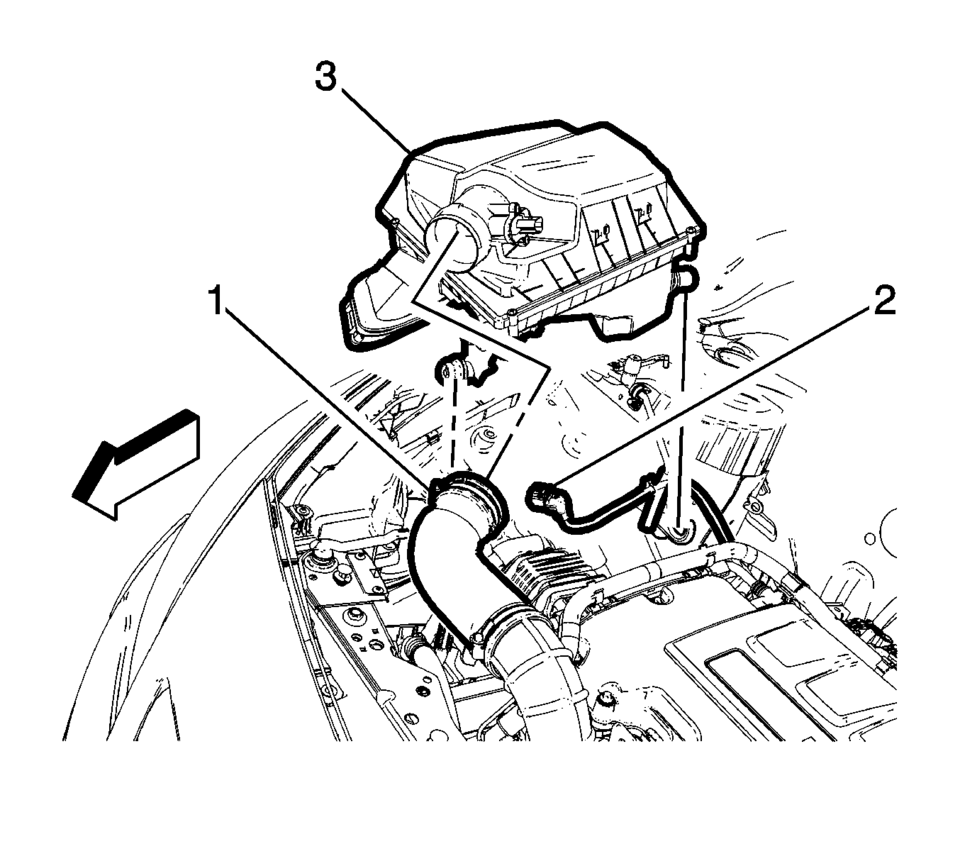
- Remove the lower intermediate steering shaft bolt (1) and slide the shaft away from steering column. Refer to Intermediate Steering Shaft Replacement.
- Remove the air cleaner assembly (1). Refer to Air Cleaner Assembly Replacement.
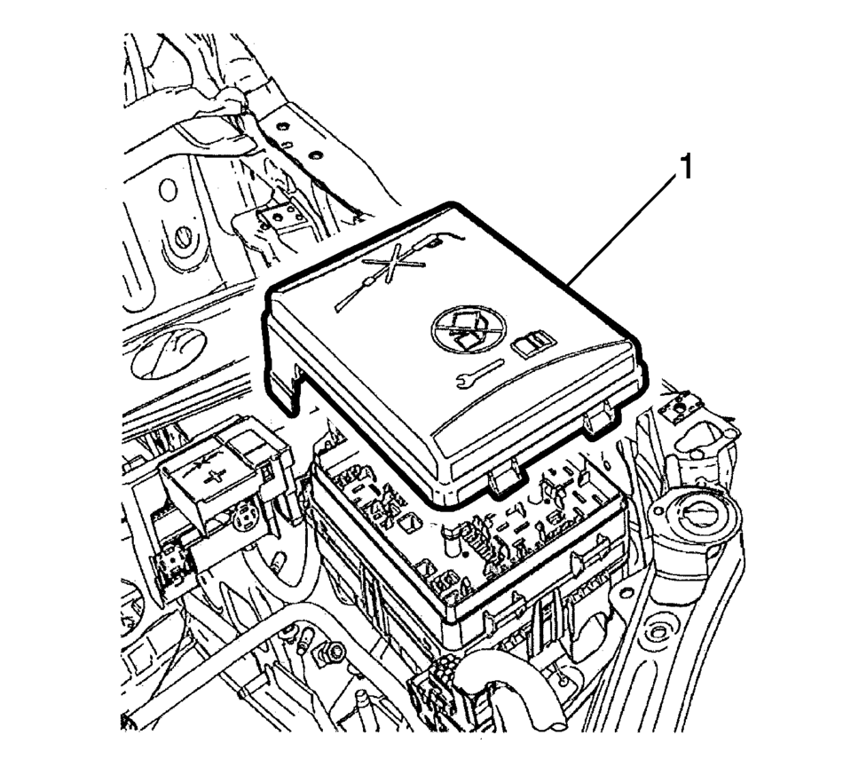
- Remove the junction block cover (1).
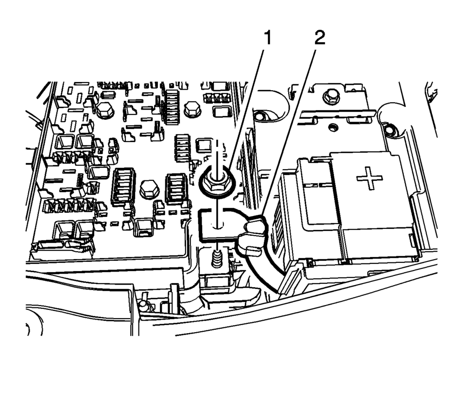
- Remove the positive battery cable nut (1) from the junction block.
- Remove the positive battery cable (2) from the junction block.
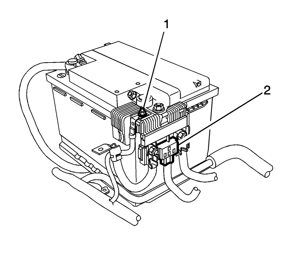
- Remove the positive cable nut (1) and battery positive cable, from the battery positive cable junction block.
- Disconnect the body wiring master harness connector (2), from the battery positive cable junction block.
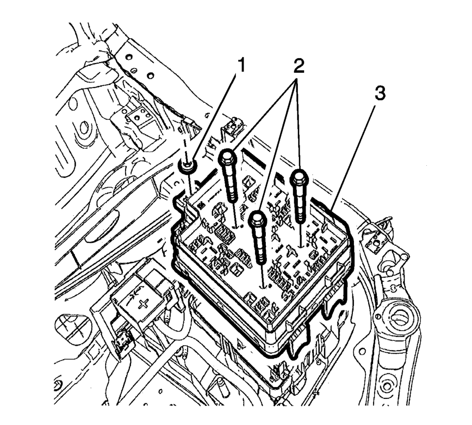
- Remove the junction block nut (1).
- Remove the junction block bolts (2).
- Disconnect the wiring harness from the junction block base.
- Remove the junction block (3) from the base.
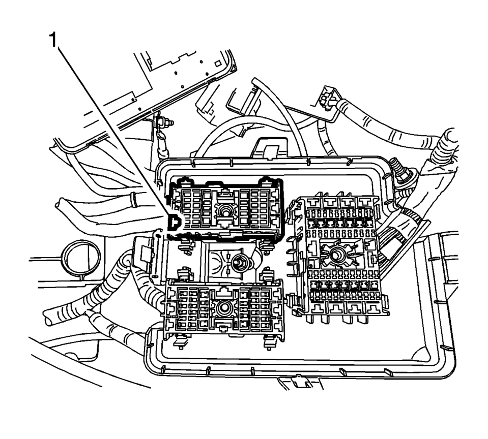
- Disconnect the wiring harness plug from the front compartment fuse block.
- Reposition the wiring harness (1) on top of the engine.
- Remove the ground nuts (1) and reposition the wiring harness (2) aside.
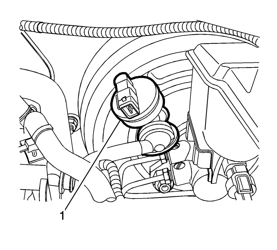
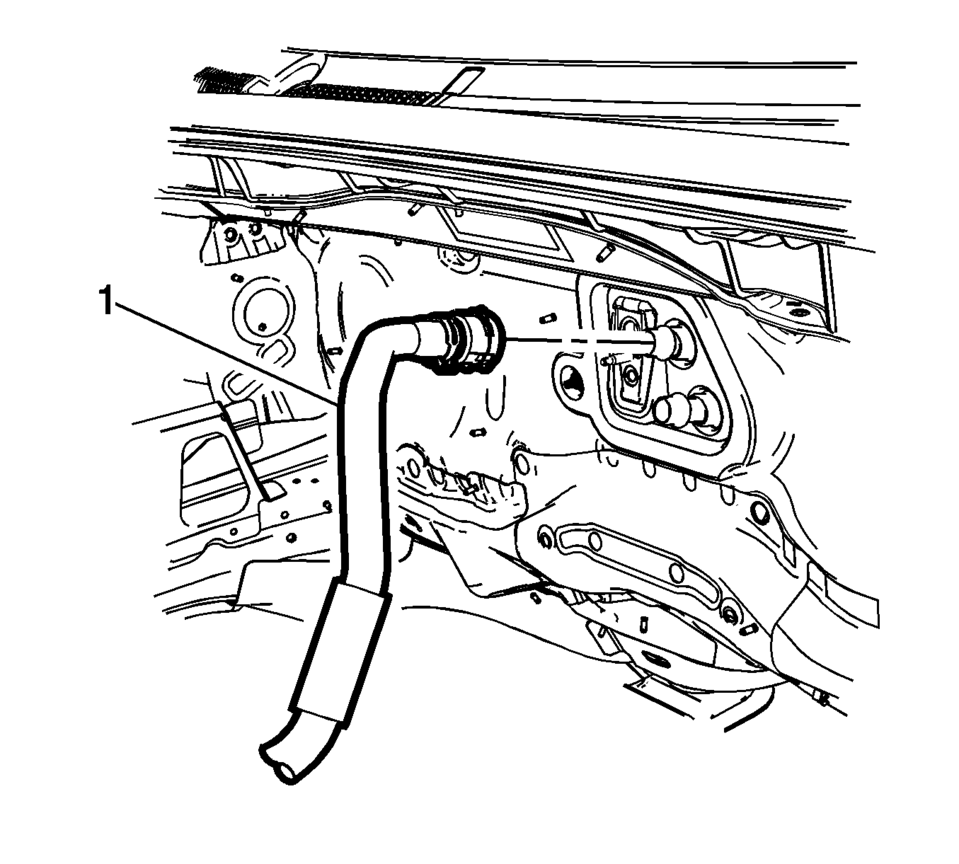
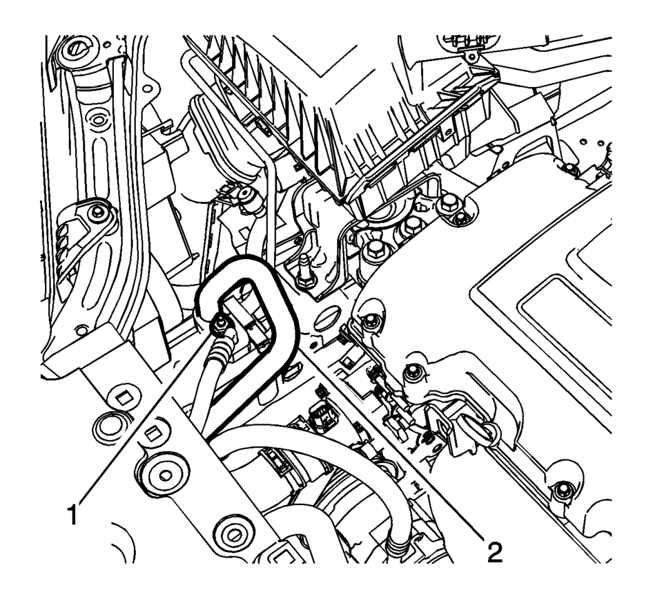
- Disconnect the electrical connector and remove the brake booster hose (1) .
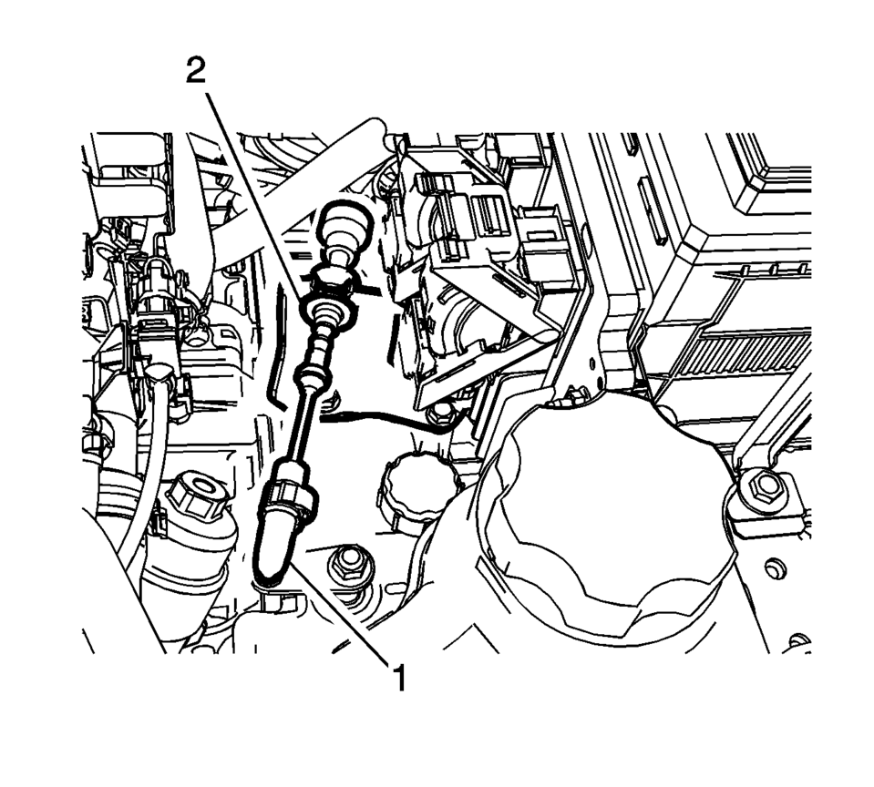
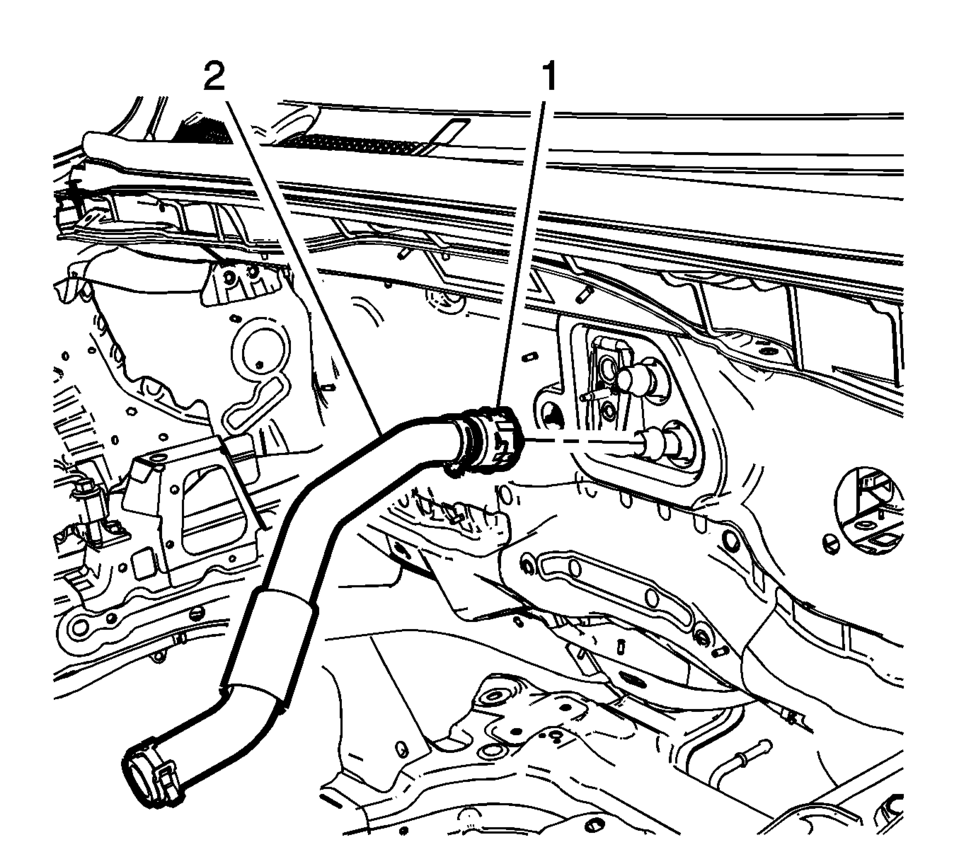
- Disconnect the heater inlet hose (1) from the heater core. Refer to Heater Inlet Hose Replacement.
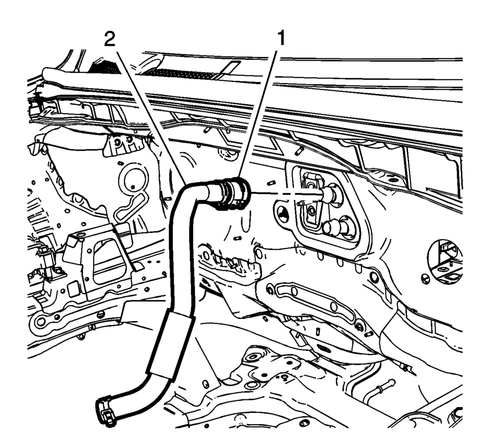
- Disconnect the heater outlet hose (1) from the heater core. Refer to Heater Outlet Hose Replacement.
- If equipped with an automatic transmission, disconnect the transmission range selector lever cable terminal (1) from the transmission manual shift lever pin.
- Remove the transmission range selector lever cable (2) from the cable bracket.
- If equipped with manual transmission, disconnect the shift lever and selector lever cable end (1) from the transmission shift lever and selector lever.
- Pull the cable retainers (2) to release the shift lever and selector lever cable from the shift lever and selector lever cable bracket.
- Disconnect the shift lever and selector lever cable from the shift lever and selector lever cable bracket.
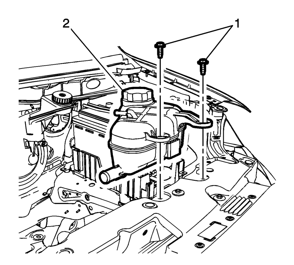
- Remove the radiator surge tank (2) and position aside. Refer to Radiator Surge Tank Replacement.
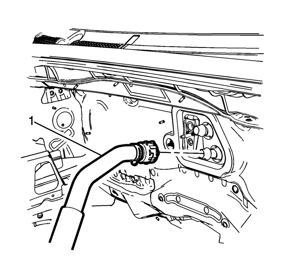
- Disconnect the fan connector.
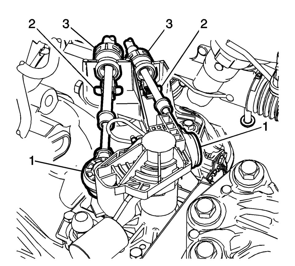
- Remove air conditioning compressor and condenser hose nut (1).
- Remove air conditioning compressor and condenser hose (2) from refrigerant hose.
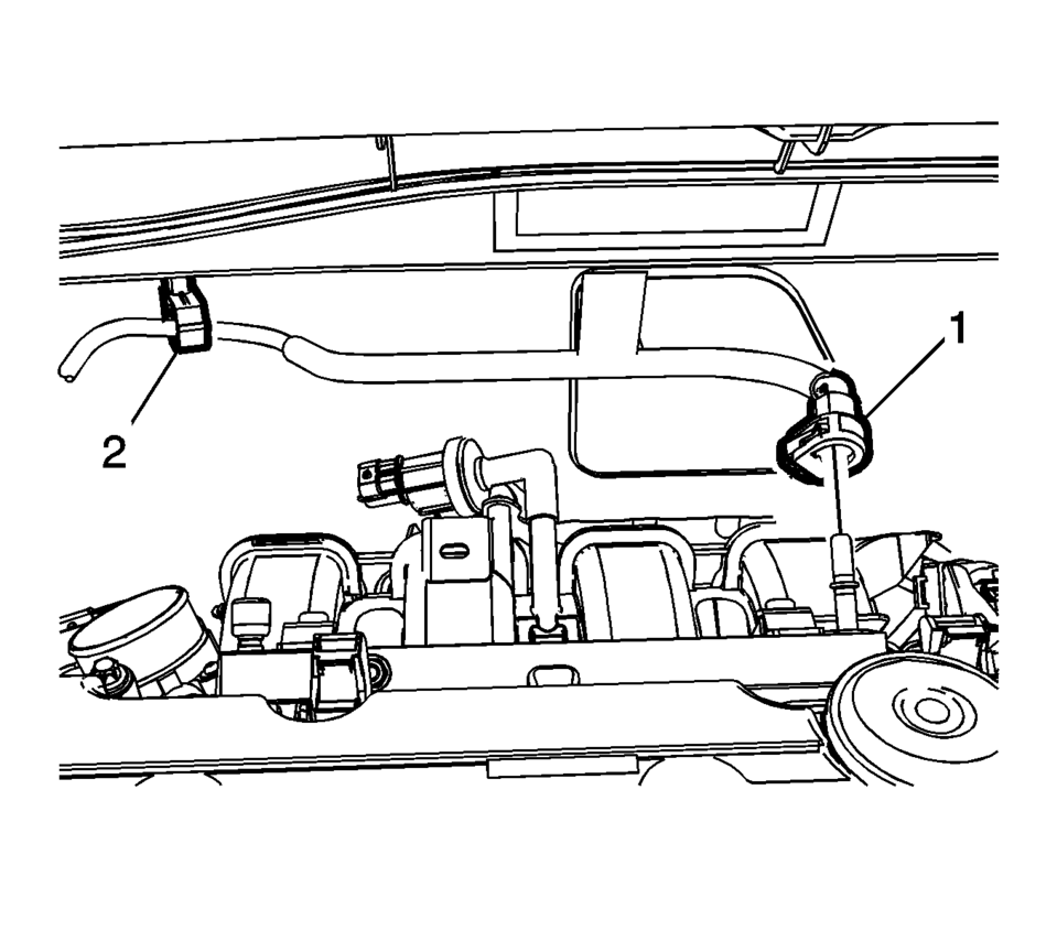
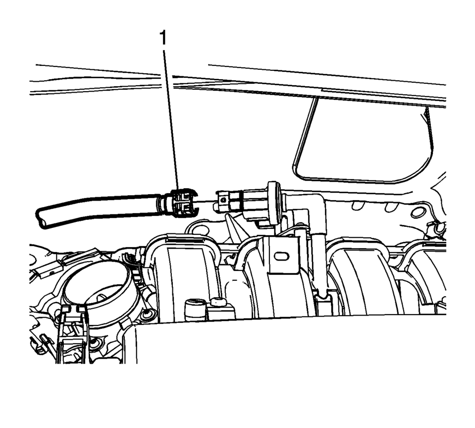
- Disconnect the fuel feed pipe (1). Refer to Plastic Collar Quick Connect Fitting Service.
- Disconnect the evaporative emission pipe (1). Refer to Plastic Collar Quick Connect Fitting Service.
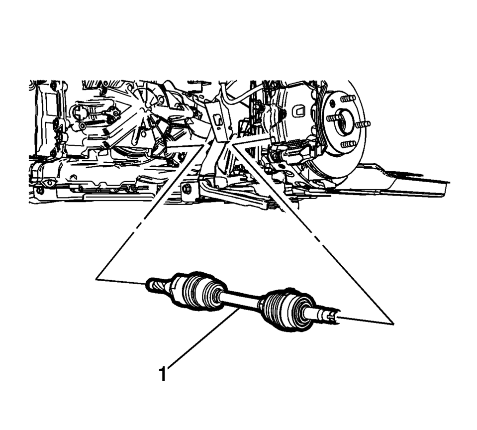
- Remove the wheel drive shafts. Refer to Front Wheel Drive Shaft Replacement.
- Remove the front exhaust pipe. Refer to Exhaust Front Pipe Replacement.
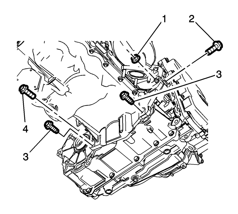
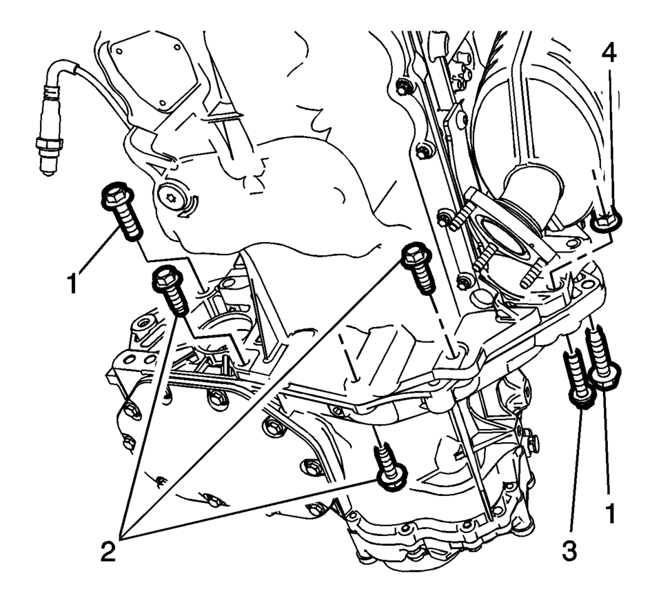
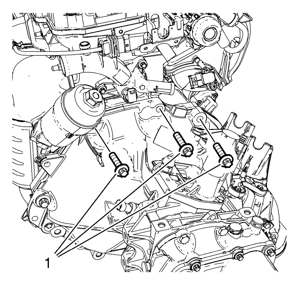
- If equipped with an automatic transmission, remove the lower transmission nut (1) and the lower transmission bolts (2, 3, 4).
- If equipped with manual transmission, remove the lower transmission bolt (3) and nut (4).
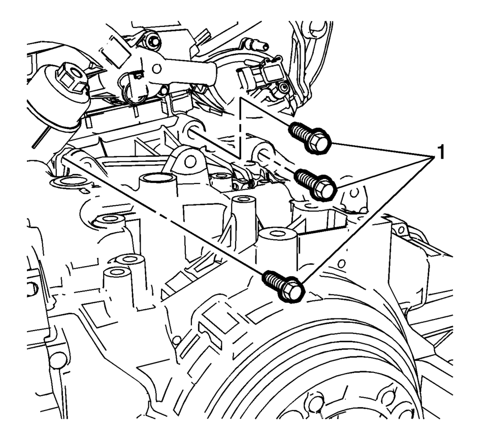
- Remove the lower transmission bolts (1, 2).
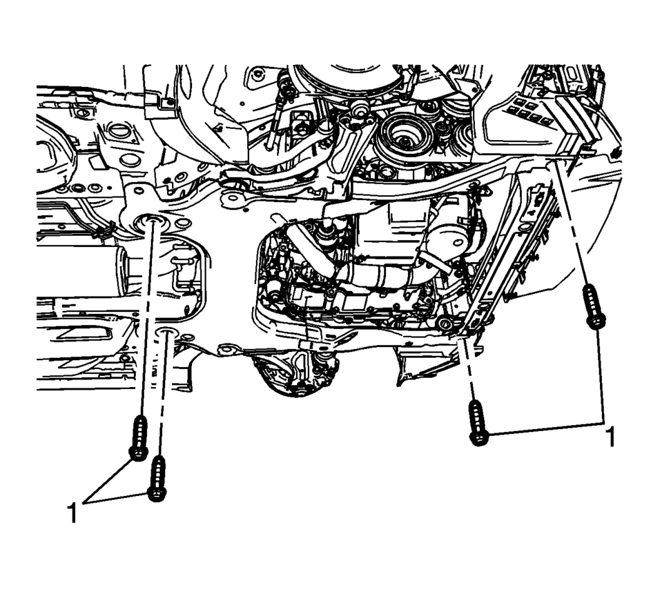
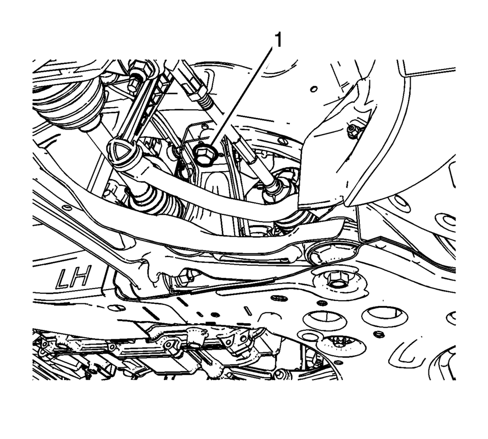
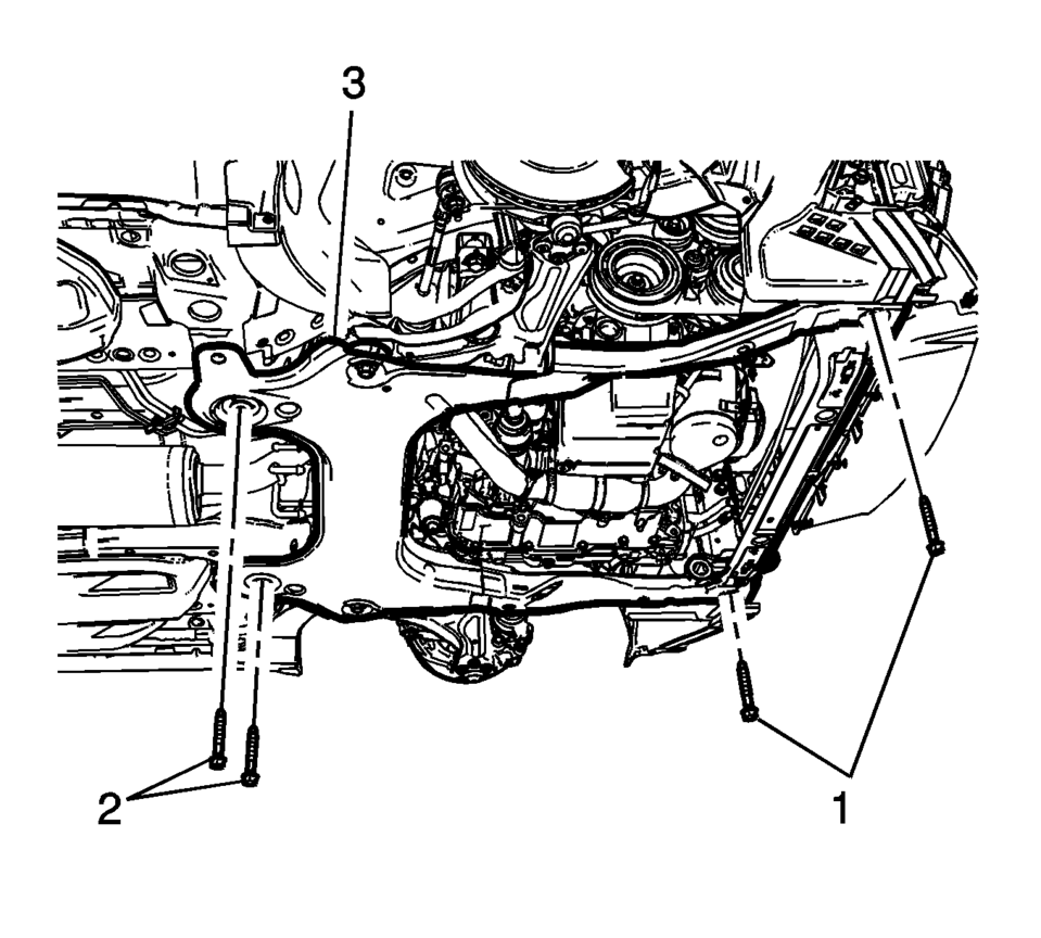
- Remove the frame front bolts (1).
- Position the EN-48244 engine assembly remove/install pallet supporter under the powertrain and support with blocks of wood.
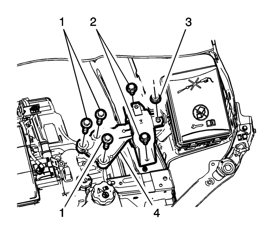
- Remove the upper frame suspension retaining bolts (1) on both sides.
- Remove the right side engine mount (4). Refer to Engine Mount Replacement - Right Side.
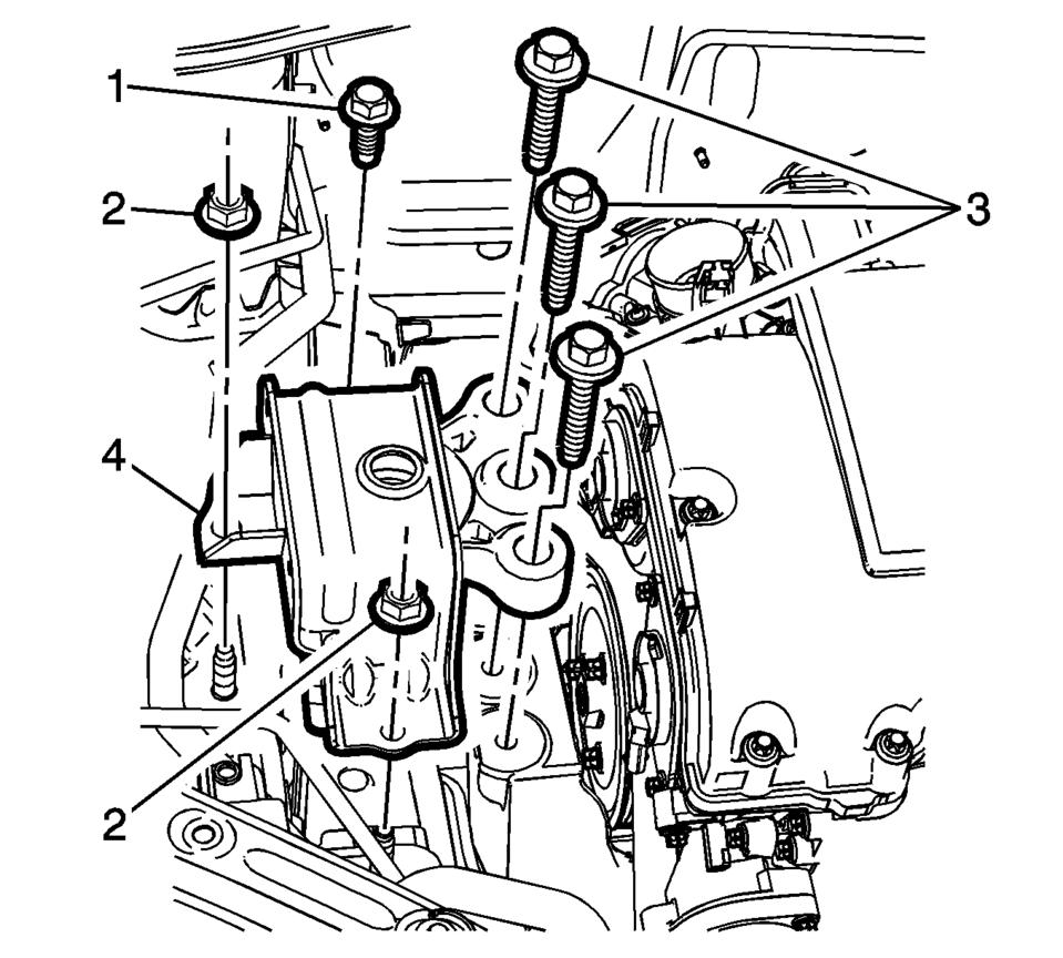
- Remove and DISCARD the transmission mount bolts (1) ?Eleft side. Refer to Transmission Mount Replacement - Left Side.
- Disconnect any additional electrical connections as necessary.
- Raise the vehicle until the powertrain is clear for removal.
- If equipped with an automatic transmission, remove the starter. Refer to Starter Replacement.
- Mark the relationship of the flex plate to the torque converter for reassembly.
- Remove and DISCARD the flex plate to torque converter bolts (1).
- If equipped with an automatic transmission, remove the upper transmission to engine bolts (1) and separate the engine and transmission.
- If equipped with manual transmission, remove the upper transmission to engine bolts (1). And separate the engine and transmission.
- Disconnect any electrical connectors as needed.
- Transfer parts as necessary.


\i
in in
- Installation Procedure
-
- Install the transmission to the engine.
- If equipped with a manual transmission, install the upper transmission
to engine bolts (1) to 60 Y(44 lb ft)
.
- If equipped with automatic transmission, install the upper transmission
to engine bolts (1) and tighten to 60 Y (44 lb ft)
.
- If equipped with an automatic transmission, install the torque converter
to flex plate bolts (1) and tighten to 60 Y (44 lb ft)
.
- Install the starter. Refer to Starter Replacement.
- Position the powertrain under the vehicle and slowly lower the body onto the powertrain.
- Install the NEW left transmission mount to transmission bolts (1) and
tighten to 50 Y (37 lb ft) plus 70 degrees
.
- Install the right side engine mount (4). Refer to Engine Mount Replacement - Right Side.
- Connect all previously disconnected electrical connections.
- Install the frame (3) rear bolts (2) and front bolts (1), tighten a little bit.
- Install the frame (3) rear bolts (2) and tighten to 135 Y (100 lb ft)
.
- Install the frame (3) front bolts (1) and tighten to 58 Y (43 lb ft)
.
- Install the upper frame suspension retaining bolts (1) on both sides
and tighten to 135 Y (100 lb ft)
.
- Remove the lift table.
- If equipped with manual transmission, install the lower transmission
bolts (1) and tighten to 60 Y (44 lb ft)
.
- Install the lower transmission bolts (2) and tighten 40 Y (30 lb ft)
.
- Install the lower transmission bolt (3) and nut (4) and tighten to
40 Y (30 lb ft)
.
- If equipped with an automatic transmission, install the lower transmission
bolts (2, 4) and tighten to 60 Y (44 lb ft)
.
- Install the lower transmission bolts (3) and the lower transmission
nut (1) and tighten to 40 Y (30 lb ft)
.
- Install the front exhaust pipe. Refer to Exhaust Front Pipe Replacement.
- Install the wheel drive shafts. Refer to Front Wheel Drive Shaft Replacement.
- Connect the evaporative emission pipe (1). Refer to Plastic Collar Quick Connect Fitting Service.
- Connect the fuel feed pipe (1). Refer to Plastic Collar Quick Connect Fitting Service.
- Install air conditioning compressor and condenser hose to the refrigerant hose.
- Install air conditioning compressor and condenser hose nut (1) tighten
nut to 22 Y (16 lb ft)
.
- Install the radiator surge tank (2). Refer to Radiator Surge Tank Replacement.
- Connect the fan connector.
- If equipped with manual transmission, Connect the shift lever and selector lever cable end (1) to the transmission shift lever and selector lever.
- Connect the shift lever and selector lever cable to the shift lever and selector lever cable bracket.
- Install the cable retainers (2) to the shift lever and selector lever cable bracket.
- If equipped with automatic transmission, install the transmission range selector lever cable (2) to the cable bracket.
- Connect the transmission range selector lever cable terminal (1) to the transmission manual shift lever pin.
- Adjust the automatic transmission range selector lever cable. Refer to Range Selector Lever Cable Adjustment.
- Connect the heater inlet hose (2) from the heater core. Refer to Heater Inlet Hose Replacement.
- Connect the heater outlet hose (2) from the heater core. Refer to Heater Outlet Hose Replacement.
- Connect the electrical connector and install the brake booster hose (1).
- Install the ground nuts (1) and wiring harness (2).
- Clip in the wiring harness plugs (1).
- Install the junction block to the base (3).
- Install the junction block bolts (2) and tighten to 5 Y (44 lb in)
.
- Install the junction block nut (1) and tighten to 5 Y (44 lb in)
.
- Install the battery positive cable to the battery positive cable junction
block and tighten nut (1) to 5 Y (44 lb in)
.
- Connect the body wiring master harness connector (2), to the battery positive cable junction block.
- Position the positive battery cable (2) to the junction block.
- Install the positive battery cable nut (1) and tighten to 7 Y (62 lb in)
.
- Install the junction block cover (1).
- Install the air cleaner assembly (1). Refer to Air Cleaner Assembly Replacement.
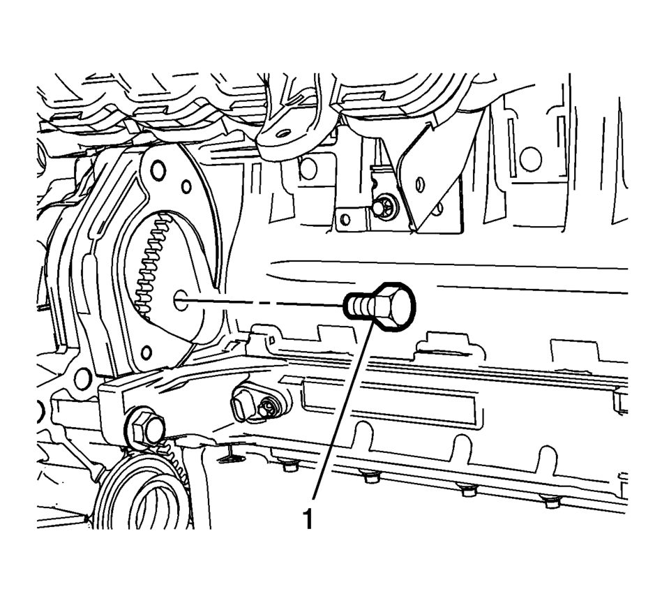
- Install the lower intermediate steering shaft bolt (1). Refer to Intermediate Steering Shaft Replacement.
- Install the battery and battery tray. Refer Battery Tray Replacement.
- Install the front tire and wheel assembly. Refer to Tire and Wheel Removal and Installation.
- Install the front bumper fascia. Refer to Front Bumper Fascia Replacement.
- Evacuate and charge the refrigerant system. Refer to Refrigerant Recovery and Recharging.
- Fill the cooling system. Refer to Cooling System Draining and Filling.
Caution:
Refer to Fastener Caution.
Caution:
Refer to Torque-to-Yield Fastener Caution.
in in
\i
 Engine Identification
Engine Number
Note: The engine identification number must be stamped to the
cylinder block in case of engine replacement.
The engine number is stamped to the engine blockR ...
 Engine Replacement (Automatic Transmission)
Special Tools
J-45859 Wheel Drive Shaft Remover
CH-807 Closure Plugs
For equivalent regional tools, refer to Special Tools.
Removal Procedure
Remove the battery and battery tra ...
Other materials:
Front Seats
The front seats have adjustable head restraints in the outboard seating positions.
Adjust the head restraint so that the top of the restraint is at the same height
as the top of the occupant's head. This position reduces the chances of a neck injury
in a crash.
The height of the head r ...
OnStar Description and Operation
This OnStar® system consists of the following components:
Telematics communication interface control module
OnStar® three button assembly
Microphone
Cellular antenna
Navigation antenna
Bluetooth® antenna (If equipped)
Back up battery (If equipped)
This system also interfaces wi ...
Front Wheel Drive Shaft Seal Replacement - Left Side
Front Wheel Drive Shaft Seal Replacement - Left Side
Callout
Component Name
Preliminary Procedures
Raise and support the vehicle. Refer to
Lifting and Jacking the Vehicle.
Remove the left wheel drive shaft. Refer to
Fr ...

0.007