Chevrolet Sonic Repair Manual: 3-5-Reverse and 4-5-6 Clutch Housing Disassemble (6T30/40/45/50 - Gen 2)
| Table 1: | Turbine Shaft, Reluctor Wheel and Piston Removal |
| Table 2: | 4?? Clutch Plate Removal |
| Table 3: | 4?? Clutch Piston Removal |
| Table 4: | Reluctor Wheel and Piston Removal |
| Table 5: | 3? Reverse Clutch Plate Removal |
- Turbine Shaft, Reluctor Wheel and Piston Removal
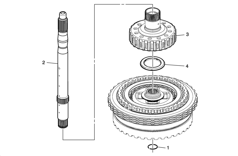
Turbine Shaft, Reluctor Wheel and Piston Removal Callout
Component Name
1
Turbine Shaft Retainer Ring
Note:
Discard the retainer ring. It is not re-usable.
Special Tools
GE 5586-A Snap Ring Pliers or equivalent
For equivalent regional tools, refer to Special Tools.
2
Turbine Shaft
3
Reaction Carrier Hub Assembly
4
Reaction Carrier Hub Thrust Bearing Assembly
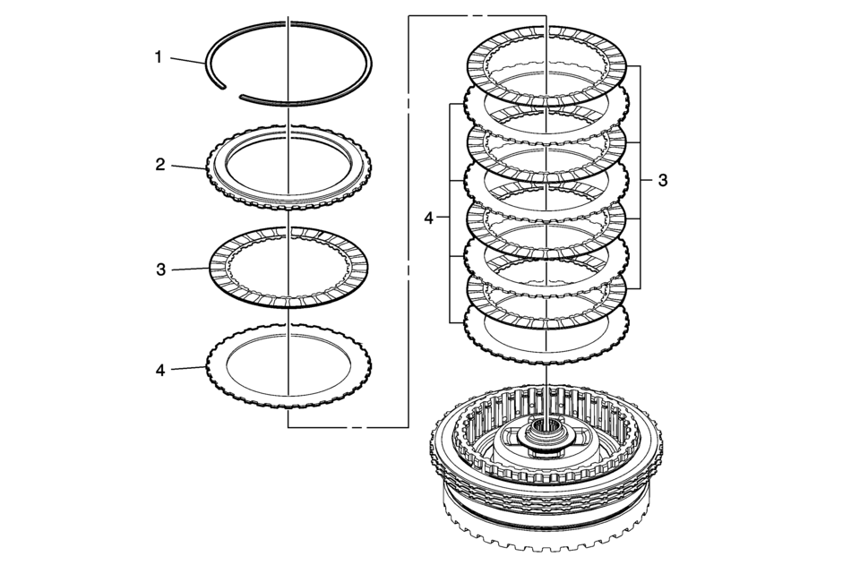
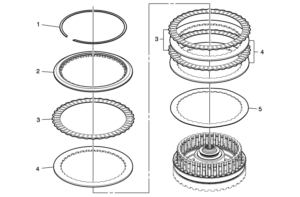
- 4?? Clutch Plate Removal
_.
4?? Clutch Plate Removal Callout
Component Name
1
4?? Clutch Backing Plate Retaining Ring
2
4?? Clutch Backing Plate
3
4?? Clutch Plate Assembly (Qty: 5)
4
4?? Clutch Plate (Gen 2 ?#8201;Qty: 5)
- 4?? Clutch Piston Removal
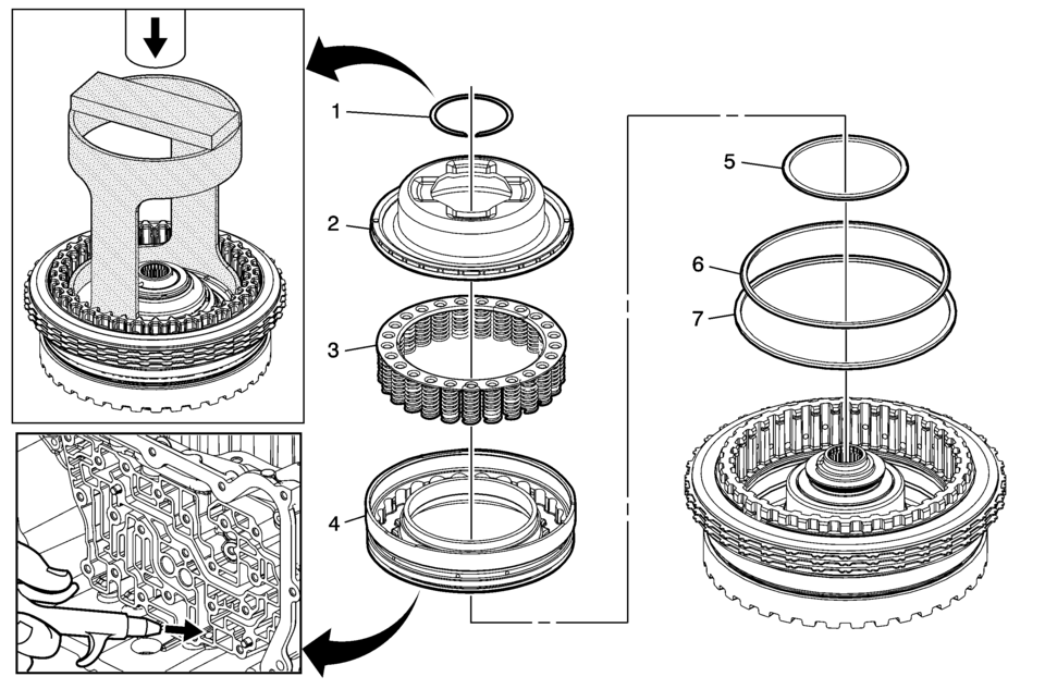
4?? Clutch Piston Removal Callout
Component Name
1
4?? Clutch Dam Retaining Ring
Special ToolsNote:
The 4-5-6 clutch dam retaining ring is not reusable.
- DT-47951-2 Spring Compressor
- GE 5586-A Snap Ring Pliers or equivalent
For equivalent regional tools, refer to Special Tools.
2
4?? Clutch Piston Fluid Dam Assembly
Procedure- Place the 3? reverse and 4?? clutch housing onto the support hub in the case.
- Apply shop air to the 4?? clutch feed hole using a rubber tipped air gun to dislodge the dam piston and the 4?? clutch piston from the clutch housing.
3
4?? Clutch Piston Return Spring Assembly
4
4?? Clutch Piston
Note:
Apply shop air to the 4?? clutch feed hole using a rubber tipped air gun to dislodge the clutch piston.
5
4?? Clutch Piston Inner Seal
6
4?? Clutch Piston Outer Seal (Dark Blue) (Stepped)
7
4?? Clutch Piston Outer Seal (Large) (Rounded)
- Reluctor Wheel and Piston Removal
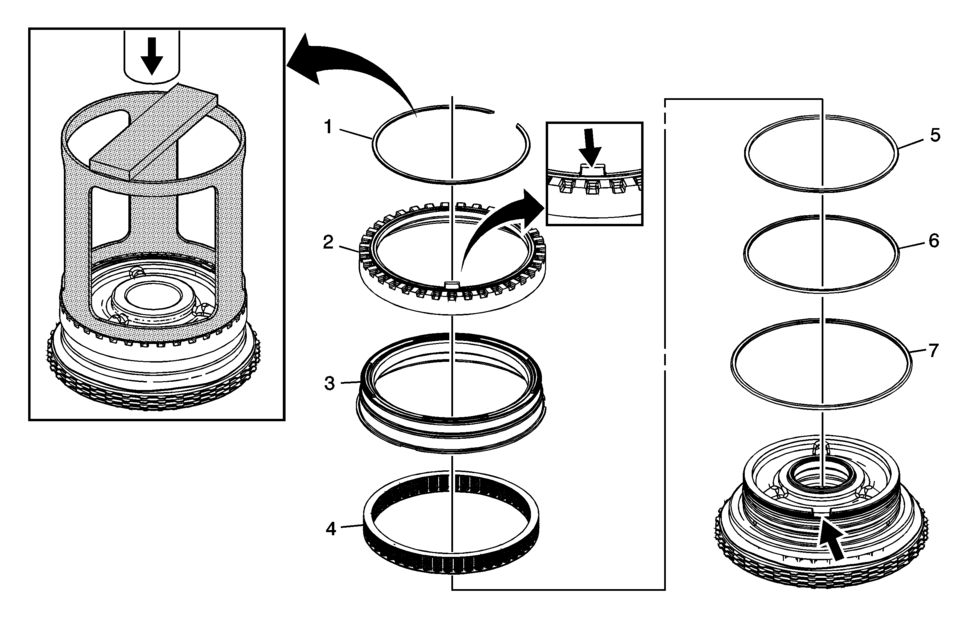
Reluctor Wheel and Piston Removal Callout
Component Name
1
Input Shaft Speed Sensor Reluctor Ring Retainer Ring
Caution:
Compress the reluctor wheel just enough to clear the retainer. Over compressing the reluctor wheel will break the alignment tab and the clutch housing.
Special Tool
DT-47694 Piston Spring Compressor
For equivalent regional tools, refer to Special Tools.
2
Input Shaft Speed Sensor Reluctor Wheel
3
3? Reverse Clutch Piston
4
3? Reverse Clutch Piston Return Spring Assembly
5
3? Reverse Clutch Piston Inner (Reluctor) Seal (Orange)
6
3? Reverse Clutch Piston Inner Seal
7
3? Reverse Clutch Piston Dam Seal (Black)
- 3? Reverse Clutch Plate Removal
3? Reverse Clutch Plate Removal Callout
Component Name
1
3? Reverse Clutch Backing Plate Ring Retainer Ring
Note:
Gently push down on the backing plate to get enough clearance between the backing plate and retainer.
2
3? Reverse Clutch Backing Plate
3
3? Reverse Clutch Plate Assembly (Qty: 3)
4
3? Reverse Clutch Plate (Qty: 3)
5
3? Reverse Clutch Apply Plate (Waved)
 3-5-Reverse and 4-5-6 Clutch Housing Assemble (6T30/40/45/50 - Gen 2)
Table 1:
4?? Clutch Piston Installation
Table 2:
4?? Clutch Fluid Dam Installation
Table 3:
3? Reverse Clutch Plates Installation
Table 4:
Reluctor Wh ...
 3-5-Reverse and 4-5-6 Clutch Housing, and Input, Reaction, and Output Carrier
Installation
3-5-Reverse and 4-5-6 Clutch Housing, and Input, Reaction, and Output Carrier
Installation
3-5-Reverse and 4-5-6 Clutch Housing, and Input, Reaction, and Output
Carrier Installation
Callout
Component Name
1
3 ...
Other materials:
Rear Side Door Window Weatherstrip Replacement (Sedan)
Rear Side Door Window Weatherstrip Replacement
Callout
Component Name
Preliminary Procedures
The rear door side window weatherstrip and window is serviced as
one assembly. Refer to Rear Side Door Stationary Window Replacement. ...
Sunroof Actuator Motor Replacement
Sunroof Actuator Motor Replacement
Callout
Component Name
Preliminary Procedure
Remove the dome lamp bezel. Refer to Dome Lamp Bezel Replacement.
1
Sunroof Actuator Motor Screw (Qty:?€‰3)
...
Transmission Disassemble (Gen 2)
Special Tools
3-9506289 Universal Adapter
R-0007758 Holding Fixture
S-9407198 Differential Bearing Race Wrench
For equivalent regional tools, refer to Special Tools.
Attach R-0007758 holding fixture (2) to the transmission.
Attach R-0007758 holding fixture (2 ...

0.0059