Chevrolet Sonic Repair Manual: Brake Rotor Thickness Measurement
Warning:
Refer to Brake Dust Warning.
- If the inboard friction surface of the brake rotor is not accessible, reposition and support the caliper with the brake pads. Refer to Front Disc Brake Pads Replacement.
- Clean the friction surfaces of the brake rotor with denatured alcohol, or an equivalent approved brake cleaner.
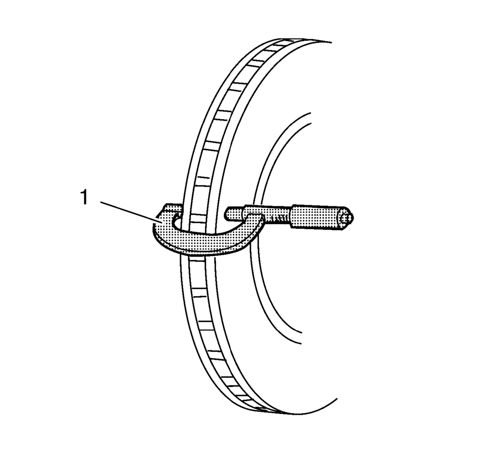
- Using a micrometer (1) calibrated in thousandths-of-a-millimeter, or ten-thousandths-of-an-inch,
measure and record the thickness of the brake rotor at four or more points,
evenly spaced around the brake rotor.
Make sure that the measurements are only taken within the friction surfaces and that the micrometer is positioned the same distance from the outer edge of the brake rotor, about 13 mm (1/2 in), for each measurement.
- Compare the lowest thickness measurement recorded to the specifications. Refer to Disc Brake Component Specifications.
- If the lowest thickness measurement of the brake rotor is above the minimum allowable thickness after refinishing specification, the brake rotor may be able to be refinished, depending upon surface and wear conditions which may be present.
- If the lowest thickness measurement of the brake rotor is at or below the discard thickness specification, the brake rotor requires replacement.
 Brake Rotor Surface and Wear Inspection
Warning: Refer to Brake Dust Warning.
If the inboard friction surface of the brake rotor is not accessible, reposition
and support the caliper with the brake pads. Refer to Front Disc Bra ...
 Brake Rotor Thickness Variation Measurement
Warning: Refer to Brake Dust Warning.
Note: Any disc brake rotor that exhibits thickness variation exceeding
the maximum acceptable level must be refinished or replaced. Thickness variati ...
Other materials:
Immobilizer Operation
This vehicle has a passive theft-deterrent system.
The system does not have to be manually armed or disarmed.
The vehicle is automatically immobilized when the key is removed from the ignition.
The system is automatically disarmed when the vehicle is started with the correct
key. The key uses a ...
Fuel Tank Heat Shield Replacement
Removal Procedure
Support the fuel tank with a suitable jack.
Remove the fuel tank strap fasteners (1) and lower the fuel tank straps (2).
Remove the fuel tank heat shield fasteners (1) and remove the fuel tank
heat shield (2).
...
Transmission Component and System Description
The mechanical components of the 6T30/40/45/50 are as follows:
A torque converter with an electronically controlled capacity clutch (ECCC)
Gear-type fluid pump assembly
1??? and low and reverse clutch housing assembly
4?? and 3? reverse clutch housing assembly
2? clutch assem ...

0.0048