Chevrolet Sonic Repair Manual: Brake Rotor Thickness Variation Measurement
Warning:
Refer to Brake Dust Warning.
Note:
Any disc brake rotor that exhibits thickness variation exceeding the maximum acceptable level must be refinished or replaced. Thickness variation exceeding the maximum acceptable level can cause brake pulsation.
- If the inboard friction surface of the brake rotor is not accessible, reposition and support the caliper with the brake pads. Refer to Front Disc Brake Pads Replacement.
- Clean the friction surfaces of the brake rotor with denatured alcohol, or an equivalent approved brake cleaner.
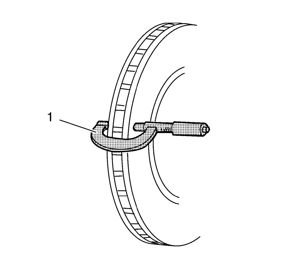
- Using a micrometer (1) calibrated in thousandths-of-a-millimeter, or ten-thousandths-of-an-inch,
measure and record the thickness of the brake rotor at 4 or more points, evenly
spaced around the brake rotor.
Make sure that the measurements are only taken within the friction surfaces and that the micrometer is positioned the same distance from the outer edge of the brake rotor, about 13 mm (1/2 in), for each measurement.
- Calculate the difference between the highest and lowest thickness measurements recorded to obtain the amount of thickness variation.
- Compare the thickness variation measurement to the following specification:
Specification
- J93, J94: 0.02 mm (0.0008 in)
- JPW, J97: 0.02 mm (0.0008 in)
- J93, J94: 0.02 mm (0.0008 in)
- If the brake rotor thickness variation measurement exceeds the specification, the brake rotor requires refinishing or replacement.
Note:
Whenever a brake rotor is refinished or replaced, the assembled lateral runout (LRO) of the brake rotor must be measured to make sure optimum performance of the disc brakes.
 Brake Rotor Thickness Measurement
Warning: Refer to Brake Dust Warning.
If the inboard friction surface of the brake rotor is not accessible, reposition
and support the caliper with the brake pads. Refer to Front Disc Bra ...
 Brake Rotor/Drum Balance Inspection
Support the vehicle drive axle on a suitable hoist. Refer to Lifting and
Jacking the Vehicle.
Remove the tire and wheel assemblies from the drive axle. Refer to Tire
and Wheel Removal and ...
Other materials:
Rear Seat Cushion Removal and Installation
Rear Seat Cushion Removal and Installation
Callout
Component Name
1
Rear Seat Cushion Replacement
Procedure
Release the rear seat center seat belts.
Lift up on the front of the seat cushion at the latch locati ...
Engine Front Cover with Oil Pump Replacement
Removal Procedure
Disconnect the battery negative cable. Refer to Battery Negative Cable
Disconnection and Connection.
Set the engine to TDC. Refer to Camshaft Timing Chain Inspection.
Raise and support the vehicle. Refer to Lifting and Jacking the Vehicle.
Remove ...
Overview
The Nissan Armada ProPILOT Assist system is an advanced driver assistance technology
designed specifically for controlled-access highways. It is not intended for urban
streets or rural roads. This system supports the driver by helping maintain lane
centering and keeping a preset following dist ...

0.0069