Chevrolet Sonic Repair Manual: Cylinder Head Disassemble
Special Tools
- EN-840 Pliers/Remover
- EN-8062 Valve Spring Compressor
- EN-8062-5 Adapter
- EN-50717-2 Compressor Assembly of EN-50717 Kit
For equivalent regional tools, refer to Special Tools.
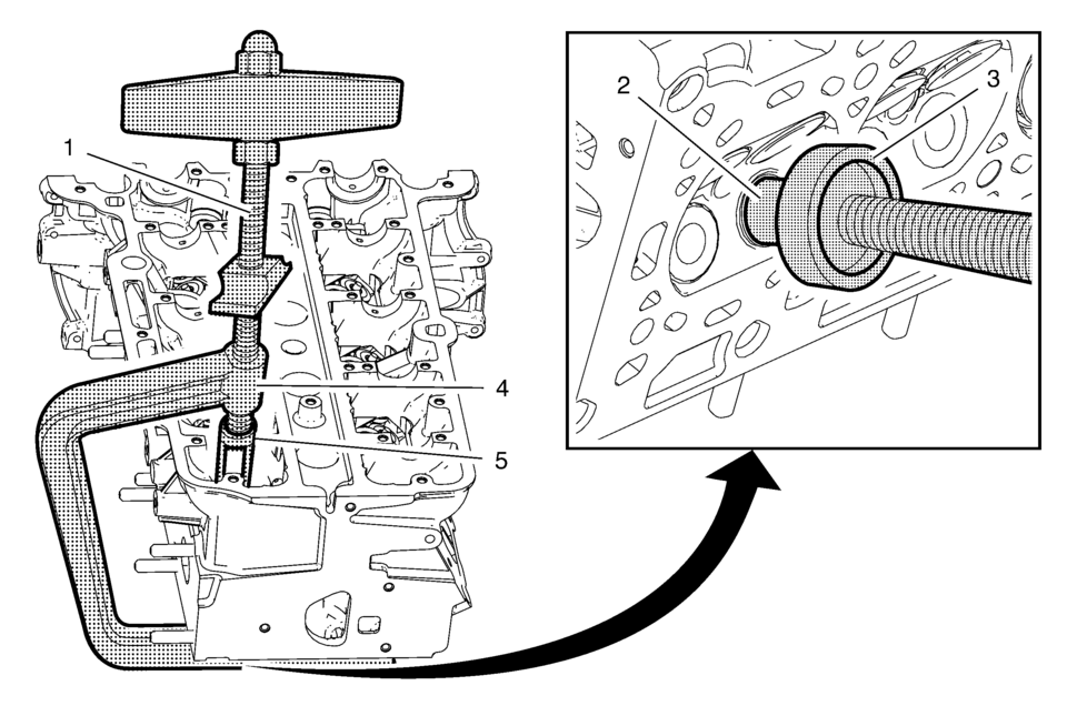
- Install the EN-50717?E assembly (1) to the EN-8062 compressor (4).
- Install the EN-8062?E adapter (3) to the EN-8062 compressor.
- Install the compressor assembly to the cylinder head, so that the adapter (5) of the EN-50717?E assembly (1) contacts the valve spring retainer properly and the EN-8062?E adapter (3) contacts the valve disc (2). Prefix the EN-8062 compressor (4).
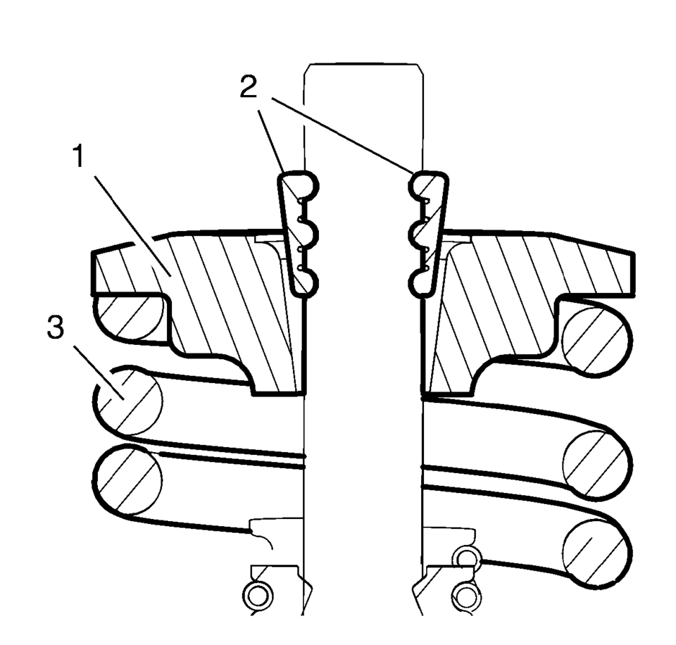
- Apply pressure to the EN-50717?E assembly to push down the vale spring retainer (1) and compress the valve spring (3) until the valve keys (2) are free from tension. Carefully remove the valve keys.
- Slowly and carefully loosen the EN-50717?E assembly until the valve spring is entirely expanded.
- Remove the compressor assembly from the cylinder head.
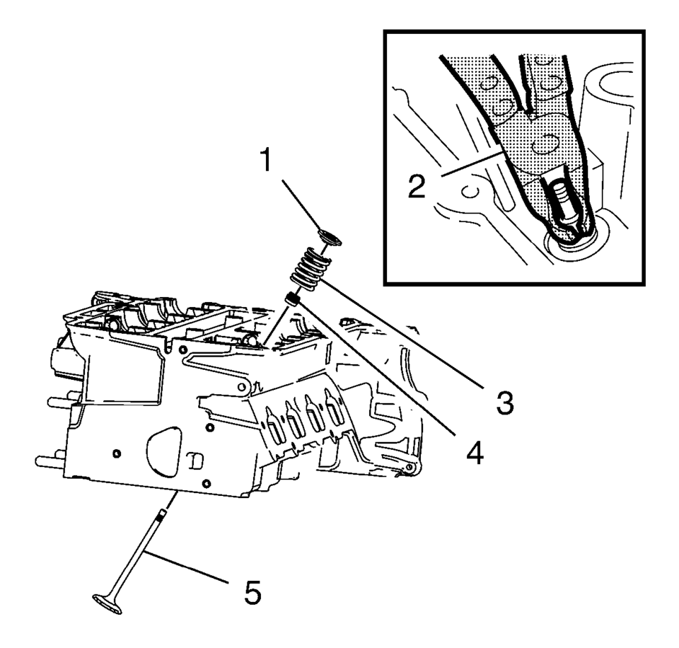
- Remove the valve spring retainer (1) and the valve spring (3).
- Remove and DISCARD the valve stem oil seal (4), using the EN-840 pliers (2).
- Remove the valve (5).
- Repeat the procedure with the remaining valves.
- In case of re-using the cylinder head, refer to Cylinder Head Cleaning and Inspection.
Warning:
Valve springs can be tightly compressed. Use care when removing the retainers and plugs. Personal injury could result.
Note:
Ensure that the valve train components are kept together and identified in order for proper installation in their original position.
 Cylinder Head Cleaning and Inspection
Valve Cleaning and Inspection
Warning: Bodily injury may occur if the cleaning solvent is
inhaled or exposed to the skin.
Note: Do not scratch the valve ste ...
 Cylinder Head Installation
Special Tools
EN-45059 Torque Angle Sensor Kit
For equivalent regional tools, refer to Special Tools.
Clean the sealing surfaces.
Inspect for plane surface.
Cylinder block, cylinder h ...
Other materials:
StabiliTrak® OFF Light
This light comes on briefly while starting the engine. If it does not, have the
vehicle serviced by your dealer.
This light comes on when the StabiliTrak system is turned off. If StabiliTrak
is off, the Traction Control System (TCS) is also off.
If the StabiliTrak and TCS are off, the system ...
Rear Side Door Trim Replacement (Sedan)
Rear Side Door Trim Replacement
Callout
Component Name
1
Rear Side Door Inside Handle Bolt Cap
2
Rear Side Door Inside Handle Fastener
Caution: Refer to Fastener Caution.
Proce ...
Front Wheel Drive Shaft Seal Replacement - Case Side
Front Wheel Drive Shaft Seal Replacement - Case Side
Callout
Component Name
1
Front Wheel Drive Shaft Oil Seal
Special Tools
DT-23129 Universal Seal Remover
DT-47790 Seal Installer
GE-6125-1B Slide Hamme ...

0.0058