Chevrolet Sonic Repair Manual: Engine Front Cover and Oil Pump Cleaning and Inspection
- Engine Front Cover Cleaning Procedure
-
- Clean the engine front cover sealing surface.
- Clean the shown oil gallery with solvent and compressed air. Blow compressed air from bore (2) to bore (1).
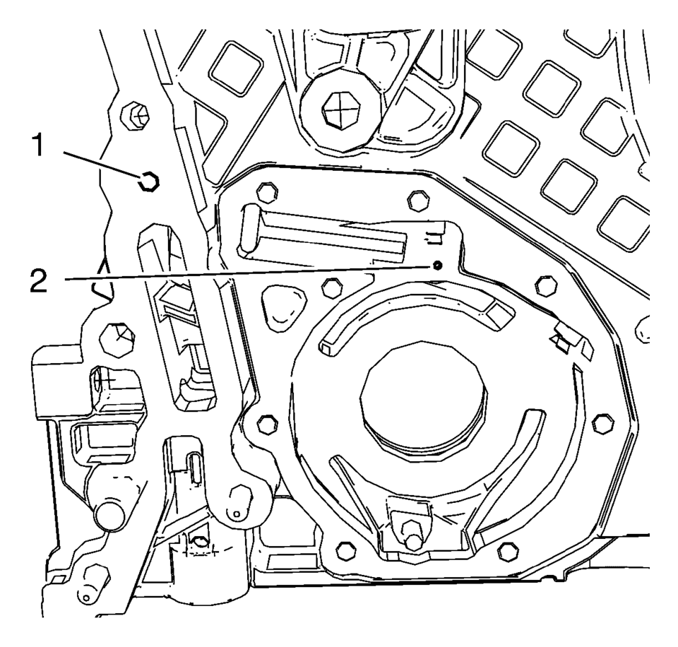
Warning:
Wear safety glasses when using compressed air in order to prevent eye injury.
Caution:
To ensure proper engine lubrication, clean clogged or contaminated oil galleries in an approved solvent and with compressed air. Failure to clean oil galleries may cause engine damage.
- Engine Front Cover Visual Inspection
-
Inspect the engine front cover for cracks, scratches and damage.
- Oil Pump Visual Inspection and Measurement
-
- Inspect the oil pump cover and the engine front cover for flatness.
- Inspect the oil pump vanes, the oil pump vane rotor, the oil pump vane rings and the oil pump slide for localized flatting.
- Inspect the oil pump slide pivot pin for firm seat.
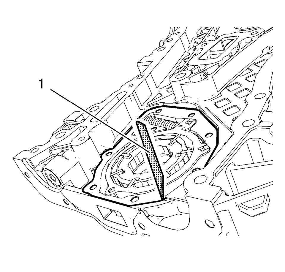
- Measure the oil pump axial clearances. Use a straight edge (1) and a feeler gauge.
- The maximal axial clearance between engine front cover and oil pump vane rotor should be 0.1 mm (0.004 in).
- The maximal axial clearance between engine front cover and oil pump vane should be 0.09 mm (0.0035 in).
- The maximal axial clearance between engine front cover and oil pump vane ring should be 0.4 mm (0.016 in).
- The maximal axial clearance between engine front cover and oil pump slide should be 0.08 mm (0.0031 in).
- The maximal axial clearance between engine front cover and oil pump slide seal should be 0.09 mm (0.0035 in).
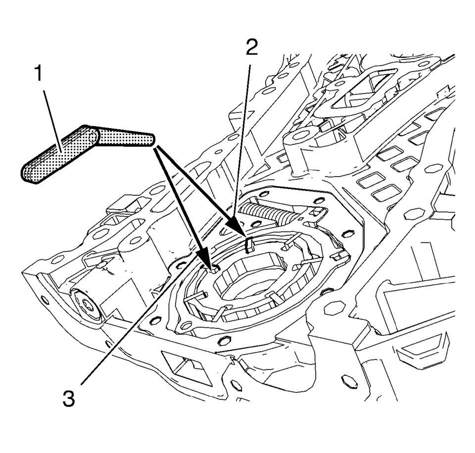
- Measure the oil pump radial clearance. Use a feeler gauge (1). Measure
the clearance between oil pump vane rotor and oil pump vane (3).
The maximal clearance should be 0.05 mm (0.002 in).
- Measure the clearance between oil pump vane and oil pump slide (2).
The maximal clearance should be 0.2 mm (0.008 in).
Note:
Oil pump components are installed.
 Engine Front Cover and Oil Pump Assemble
Oil Pump Installation
Note: The oil pump slide spring and pin, as well as the slide
seal and slide seal spring can be ordered as single parts. All other
oil pump co ...
 Engine Front Cover and Oil Pump Disassemble
Engine Front Cover Disassemble
Remove the intake camshaft position sensor bolt (1).
Remove the intake camshaft position sensor (2) and the seal ring (3).
...
Other materials:
Braking
Braking action involves perception time and reaction time. Deciding to push the
brake pedal is perception time. Actually doing it is reaction time.
Average driver reaction time is about three-quarters of a second. In that time,
a vehicle moving at 100 km/h (60 mph) travels 20m (66 ft), which co ...
Rear Disc Brake Pads Replacement
Removal Procedure
Warning: Refer to Brake Dust Warning.
Note: Always replace disc brake pads in axle sets.
Inspect the fluid level in the brake master cylinder reservoir.
If the brake fluid level is midway between the maximum-full point and
the minimum allowab ...
Wheel Drive Shafts Description and Operation
Front wheel drive axles are flexible assemblies.
Front wheel drive axles consist of the following components:
A front wheel drive shaft tripot joint (inner joint)
A front wheel drive shaft constant velocity joint (outer joint)
A front wheel drive shaft
The front wheel drive shaft connec ...

0.0057