Chevrolet Sonic Repair Manual: Engine Front Cover and Oil Pump Disassemble
- Engine Front Cover Disassemble
-
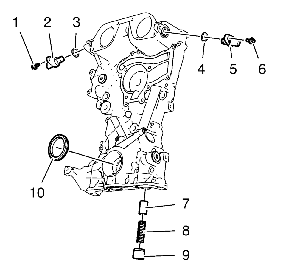
- Remove the intake camshaft position sensor bolt (1).
- Remove the intake camshaft position sensor (2) and the seal ring (3).
- Remove the exhaust camshaft position sensor bolt (6).
- Remove the exhaust camshaft position sensor (5) and the seal ring (4).
- Remove the oil pressure relief valve (7, 8 and 9)
- Remove the crankshaft front oil seal (10).
- Oil Pump Removal
-
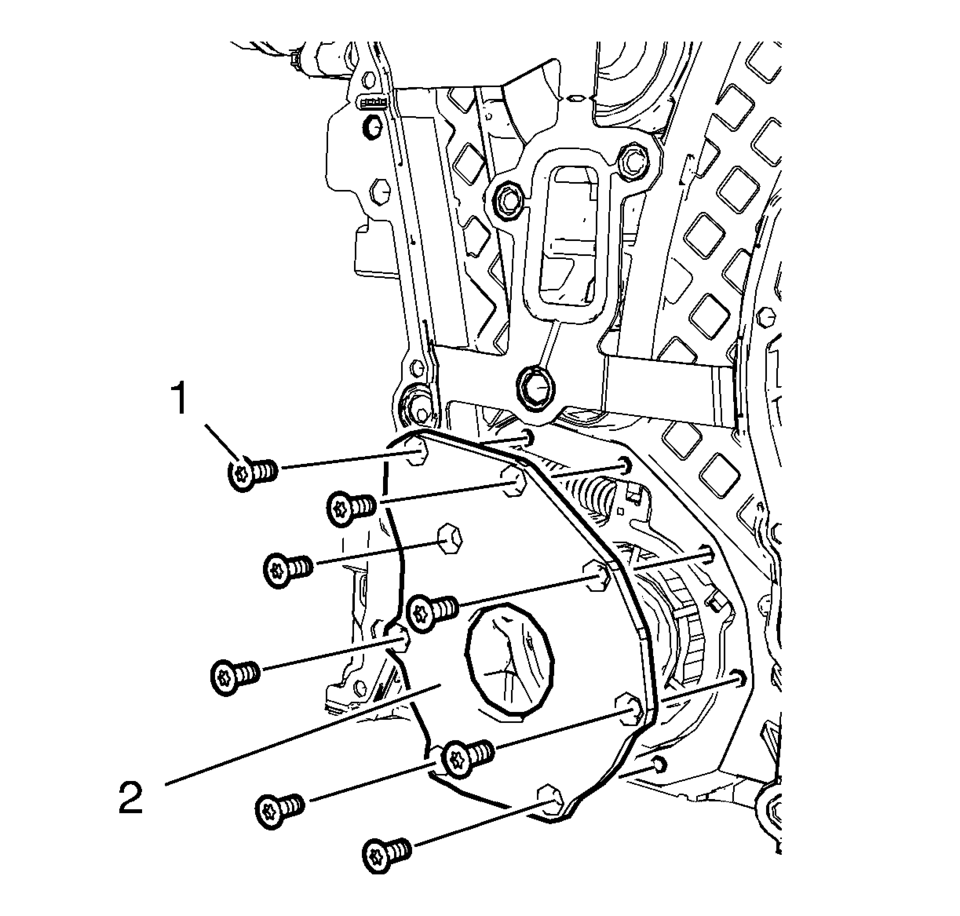
- Remove the 8 oil pump cover bolts (1).
- Remove the oil pump cover (2).
- Protect the engine front cover edge (1) with a suitable piece of plastic.
- Compress the oil pump slide spring with a screw driver and remove the oil pump slide spring along with the oil pump slide spring pin.
- Remove the oil pump components in the following order:
- Outer oil pump vane ring (1).
- Oil pump vane rotor (3) and the 7 oil pump vanes (2).
- Inner oil pump vane ring (6).
- Oil pump slide (4) and the 2 oil pump slide seals with the 2 oil pump slide seal springs (5).
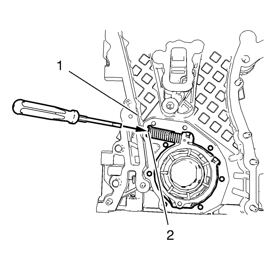
Warning:
Before removing the spring, cover the spring with a towel to prevent the spring from flying and possibly causing damage or personal injury.
Note:
Position a screw driver between the oil pump slide spring windings (2).
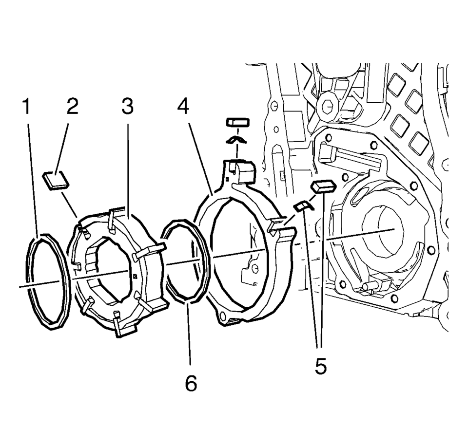
Note:
Mind the installation position of the oil pump components.
 Engine Front Cover and Oil Pump Cleaning and Inspection
Engine Front Cover Cleaning Procedure
Clean the engine front cover sealing surface.
Warning: Wear safety glasses when using compressed air in
order to prevent eye injury. ...
 Engine Front Cover and Oil Pump Installation
Special Tools
EN-952 Fixing Pin
EN-953-A Fixing Tool
EN-49977-100 Transmitter Disc Fixation
EN-49977-200 Fixing Tool
For equivalent regional tools, refer to Special Tools.
...
Other materials:
Hazard Warning Flashers
(Hazard Warning Flasher): Press
and momentarily hold this button to make the front and rear turn signal lamps flash
on and off. This warns others that you are having trouble. Press and momentarily
hold again to turn the flashers off. ...
General Information
Your vehicle is an important investment. This section describes the required
maintenance for the vehicle. Follow this schedule to help protect against major
repair expenses resulting from neglect or inadequate maintenance. It may also help
to maintain the value of the vehicle if it is sold. It ...
Instrument Panel Outer Trim Cover Replacement
Instrument Panel Outer Trim Cover Replacement
Callout
Component Name
1
Instrument Panel Outer Trim Cover (Qty:?€‰2)
Procedures
Use a flat bladed plastic trim tool in order to disengage the retainers
securi ...

0.0088