Chevrolet Sonic Repair Manual: Engine Front Cover and Oil Pump Installation
Special Tools
- EN-952 Fixing Pin
- EN-953-A Fixing Tool
- EN-49977-100 Transmitter Disc Fixation
- EN-49977-200 Fixing Tool
For equivalent regional tools, refer to Special Tools.
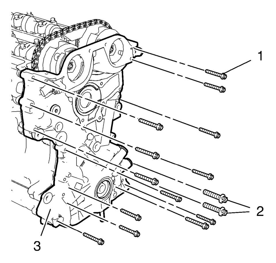
- Install the engine front cover (3).
- Install the 13 engine front cover bolts M6 (1).
- Install the 2 engine front cover bolts M10 (2).
- Tighten the 13 engine front cover bolts M6 to 8 Y (71 lb in)
.
- Tighten the 2 engine front cover bolts M10 to 35 Y (26 lb ft)
.
Note:
Mind the guide sleeves when installing engine front cover.
Caution:
Refer to Fastener Caution.
- Camshaft Sprocket Fastening
-
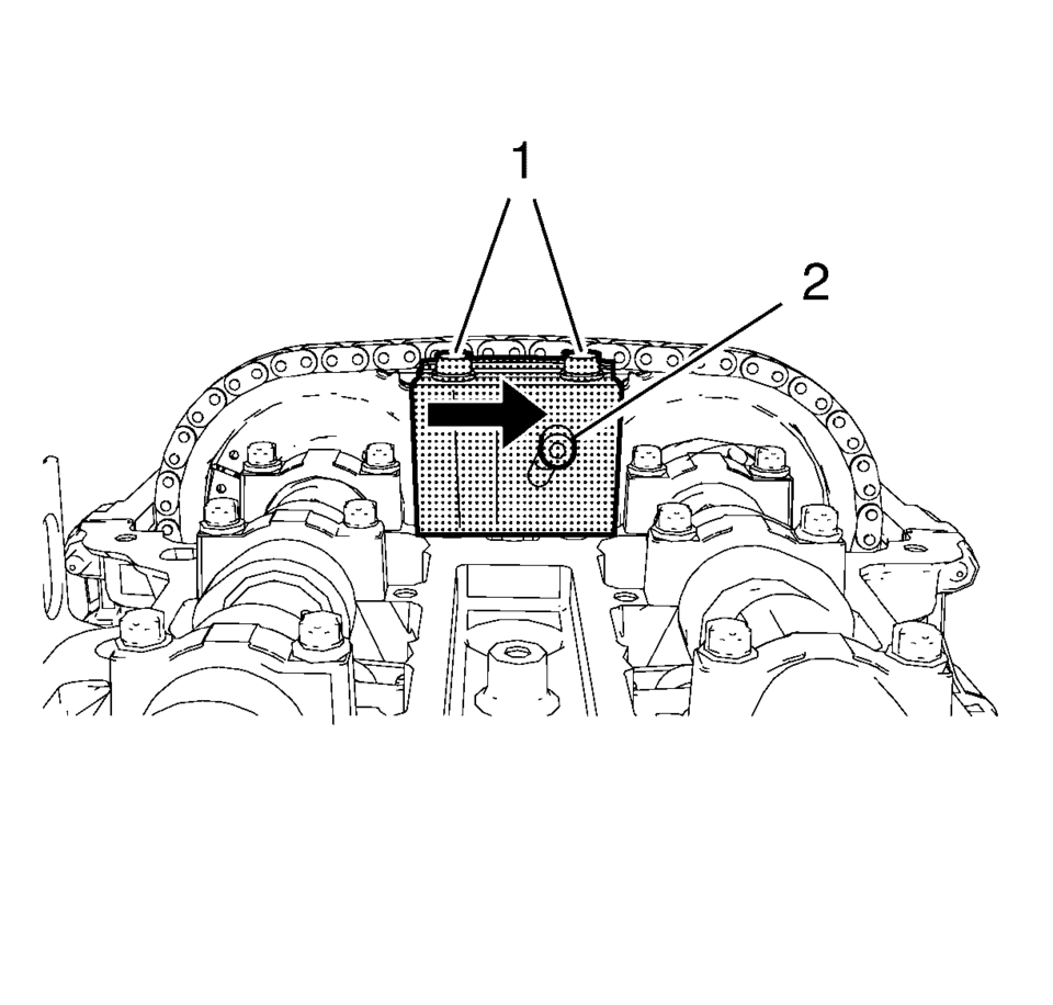
- Install EN-49977-200 fixing tool (2) and ensure that the gearing of the fixing tool engages with the intake camshaft sprocket gearing (1).
- Tighten the 2 fastening bolts (1) of EN-49977-200 fixing tool while pushing the fixing tool in direction of the arrow.
- Tighten the adjuster bolt (2).
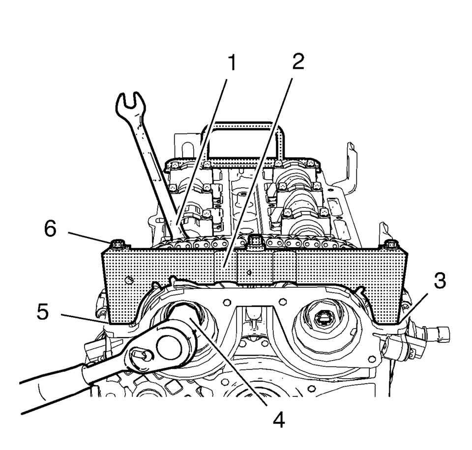
- Install EN-49977?E00 transmitter disc holder (2) to find and hold the correct position of the camshaft position exciter wheels.
- Tighten the fastening bolts (6) of EN-49977-100 transmitter disc holder.
- Tighten the NEW intake camshaft sprocket bolt (4) while holding the
hexagon (1) of the intake camshaft to 50 Y (37 lb ft)
.
- Tighten the intake camshaft sprocket bolt (4) while holding the hexagon (1)
of the intake camshaft to an additional 60 degrees
.
- Tighten the NEW exhaust camshaft sprocket bolt while holding the hexagon
of the exhaust camshaft to 50 Y (37 lb ft)
.
- Tighten the exhaust camshaft sprocket bolt while holding the hexagon
of the exhaust camshaft to an additional 60 degrees
.
- Remove EN-49977-100 transmitter disc holder and EN-49977-200 fixing tool.
Note:
Push the fixing tool in the direction of the arrow to ensure it fully engages.
Note:
A wrong installation position is possible. Make sure that the holding tool is fully installed to the cylinder head in areas (3) and (5).
Caution:
Refer to Fastener Caution.
Caution:
Refer to Torque-to-Yield Fastener Caution.
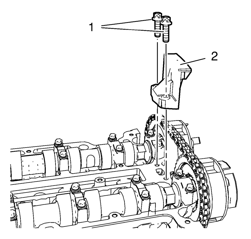
- Upper Timing Chain Guide Installation
-
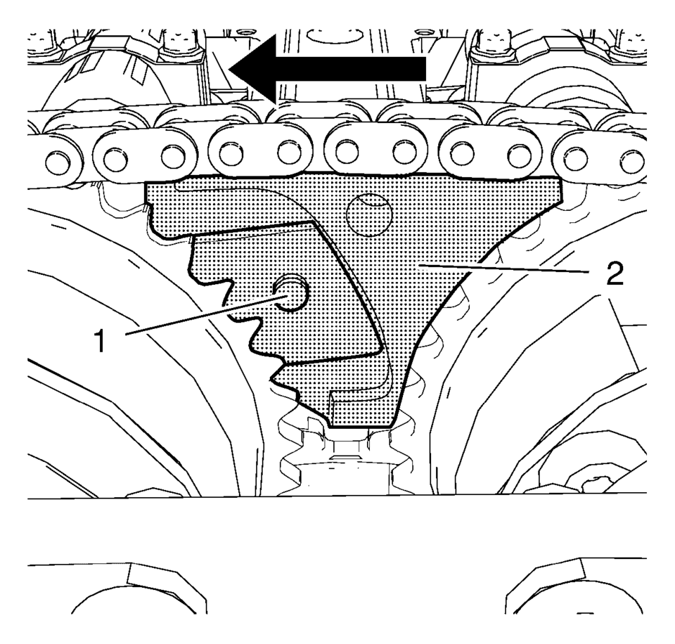
- Install the upper timing chain guide (2).
- Install the 2 upper timing chain guide bolts (1) and tighten to 8 Y (71 lb in)
.
- Remove EN-953-A fixing tool and EN-952 fixing pin.
- Install crankshaft bearing cap tie plate hole plug and seal ring and
tighten to 50 Y (37 lb ft)
.
 Engine Front Cover and Oil Pump Disassemble
Engine Front Cover Disassemble
Remove the intake camshaft position sensor bolt (1).
Remove the intake camshaft position sensor (2) and the seal ring (3).
...
 Engine Front Cover and Oil Pump Removal
Set engine to TDC. Refer to Camshaft Timing Chain Inspection.
Remove the 13 engine front cover bolts M6 (1).
Remove the 2 engine front cover bolts M10 (2).
...
Other materials:
Cargo Center Courtesy Lamp Bulb Replacement (Hatchback)
Cargo Center Courtesy Lamp Bulb Replacement
Callout
Component Name
1
Rear Compartment Courtesy Lamp
Refer to Rear Compartment Courtesy Lamp Replacement
2
Cargo Lamp Bulb
...
Stop and Turn Signal Lamp Bulb Replacement (Sedan)
Stop and Turn Signal Lamp Bulb Replacement
Callout
Component Name
Preliminary Procedure
Remove the tail lamp assembly. Refer to Tail Lamp Replacement.
1
Tail Lamp Socket
Procedure
Rotate the ...
Rear Seat Head Restraint Guide Replacement
Rear Seat Head Restraint Guide Replacement
Callout
Component Name
Preliminary Procedure
Remove the rear seat head restraint. Refer to Rear Seat Head Restraint
Replacement
1
Rear Seat Head Restra ...

0.0121