Chevrolet Sonic Repair Manual: Front Brake Caliper Replacement
- Removal Procedure
-
Warning:
Refer to Brake Dust Warning.
Warning:
Refer to Brake Fluid Irritant Warning.
- Raise and support the vehicle. Refer to Lifting and Jacking the Vehicle.
- Remove the tire and wheel assembly. Refer to Tire and Wheel Removal and Installation.
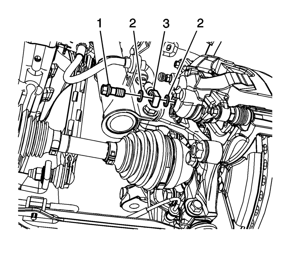
- Remove the brake hose fitting bolt (1).
- Remove and discard the brake hose fitting gaskets (2) from the brake hose fitting (3).
- Cap the brake hose fitting to prevent brake fluid loss and contamination.
- DO NOT use any air tools to remove or install the guide pin bolts. Use hand tools ONLY.
- Install an open end wrench to hold the caliper guide pin in line with the brake caliper while removing or installing the caliper guide pin bolt. DO NOT allow the open end wrench to come in contact with the brake caliper. Allowing the open end wrench to come in contact with the brake caliper will cause a pulsation when the brakes are applied.
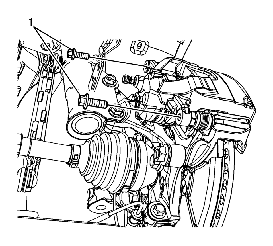
- Using a backup wrench to hold the brake caliper guide pin stationary, remove the brake caliper guide pin bolts (1).
- Remove the brake caliper.
Note:
Do not reuse the brake hose fitting gaskets.
Note:
- Installation Procedure
-
- Position the brake caliper over the brake pads and to the caliper bracket.
- Using a backup wrench to hold the brake caliper guide pin stationary,
install the brake caliper guide pin bolts (1) and tighten to 28 Y (21 lb ft)
.
- Assemble the brake hose fitting bolt (1) and the 2 new brake hose fitting gaskets (2) to the brake hose fitting (3).
- Install the brake hose assembly and tighten the brake hose fitting bolt
to 40 Y (30 lb ft)
.
- Bleed the hydraulic brake system. Refer to Hydraulic Brake System Bleeding.
- Install the tire and wheel assembly. Refer to Tire and Wheel Removal and Installation.
Caution:
Refer to Fastener Caution.
Note:
Install new brake hose fitting gaskets.
 Front Brake Caliper Overhaul
Disassembly Procedure
Warning: Refer to Brake Dust Warning.
Warning: Refer to Brake Fluid Irritant Warning.
Warning: Do not place fingers in front of the caliper ...
 Front Seat Belt Anchor Plate Tensioner Cover Replacement (4 Way)
Front Seat Belt Anchor Plate Tensioner Cover Replacement
Callout
Component Name
1
Driver or Passenger Seat Belt Tensione ...
Other materials:
Tires and Wheels Description and Operation
There are two types of tire and wheel balancing: static and dynamic.
Static balance is the equal distribution of weight around the wheel. Assemblies
that are statically unbalanced cause a bouncing action called wheel tramp. This
condition may eventually cause uneven tire wear.
...
Engine Replacement
Special Tools
EN-48244 Engine Assembly Remove/Install Pallet Supporter
Removal Procedure
Remove the battery and battery tray. Refer to Battery Tray Replacement.
Relieve the fuel system pressure. Refer to Fuel Pressure Relief.
Recover the refrigerant. Refer to Refrigera ...
Fuel Injector Replacement
Fuel Injector Replacement
Callout
Component Name
Preliminary Procedure
Disconnect battery negative cable. Refer to Battery Negative Cable
Disconnection and Connection.
Remove the fuel injection fuel rail assembly. Refer t ...

0.0064