Chevrolet Sonic Repair Manual: Front Wheel Bearing and Hub Replacement
Special Tools
CH-50559 Wheel Hub/Bearing Remover Kit
For equivalent regional tools, refer to Special Tools.
- Removal Procedure
-
- Raise and support the vehicle. Refer to Lifting and Jacking the Vehicle.
- Remove the steering knuckle assembly from the vehicle. Refer to Steering Knuckle Replacement.
- Position the steering knuckle assembly (1) in a suitable vise.
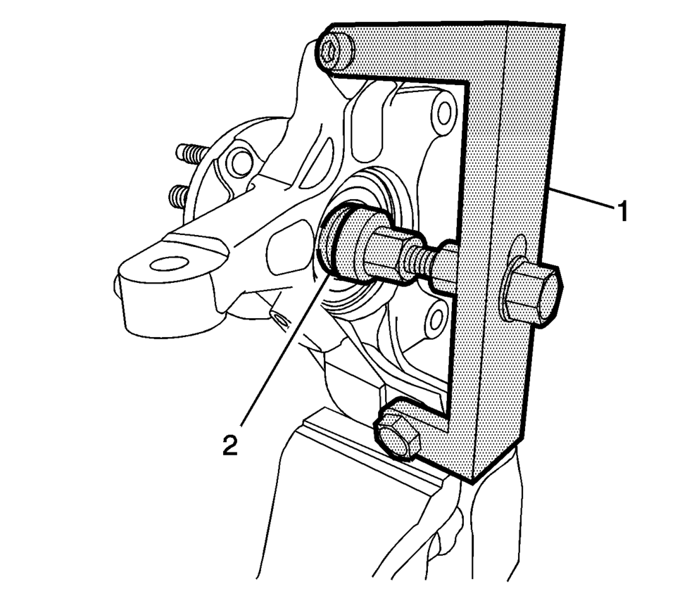
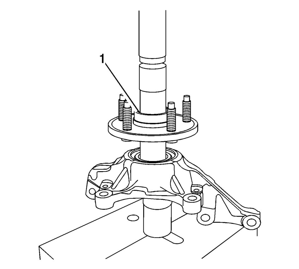
- Position the CH-50059-1 wheel hub/bearing removal/installation bridge assembly (1) and the CH-50559-2 wheel hub/bearing removal/installation adapter (2) on the wheel bearing inner hub.
- Using the CH-50059-1 and the CH-50559-2 , remove the wheel hub from the wheel bearing.
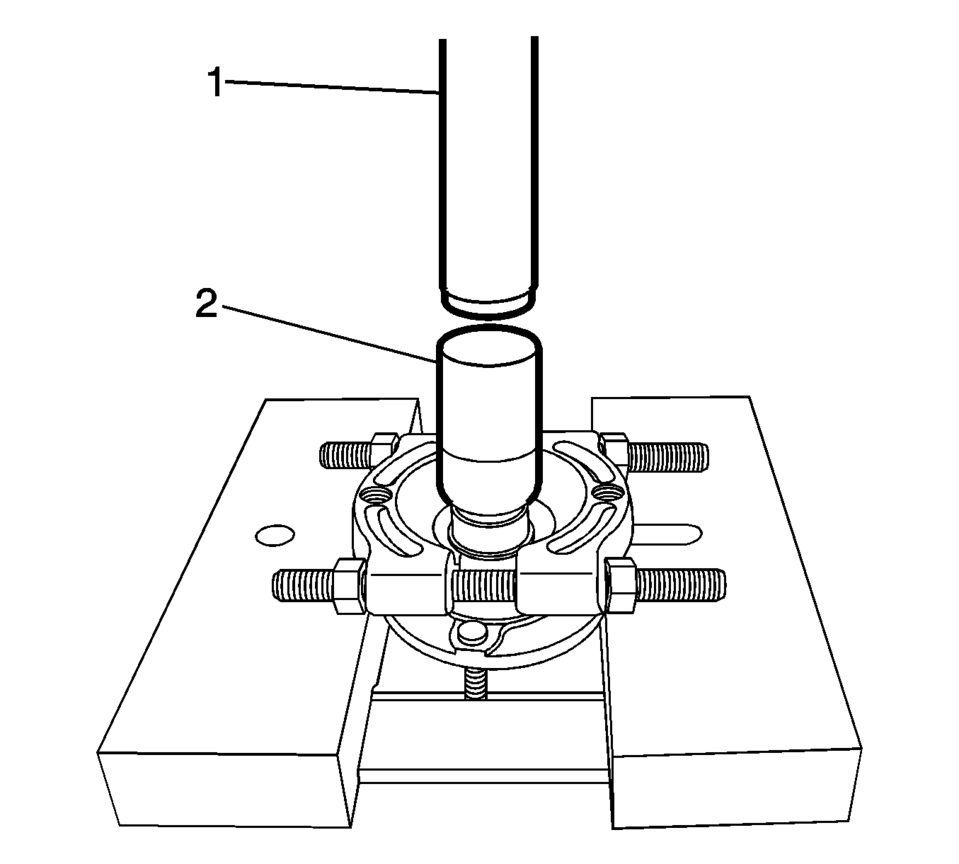
- If the inner race of the bearing is pulled out with the hub, remove the inner race from the using the appropriate tools (1, 2).
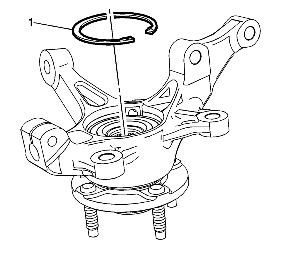
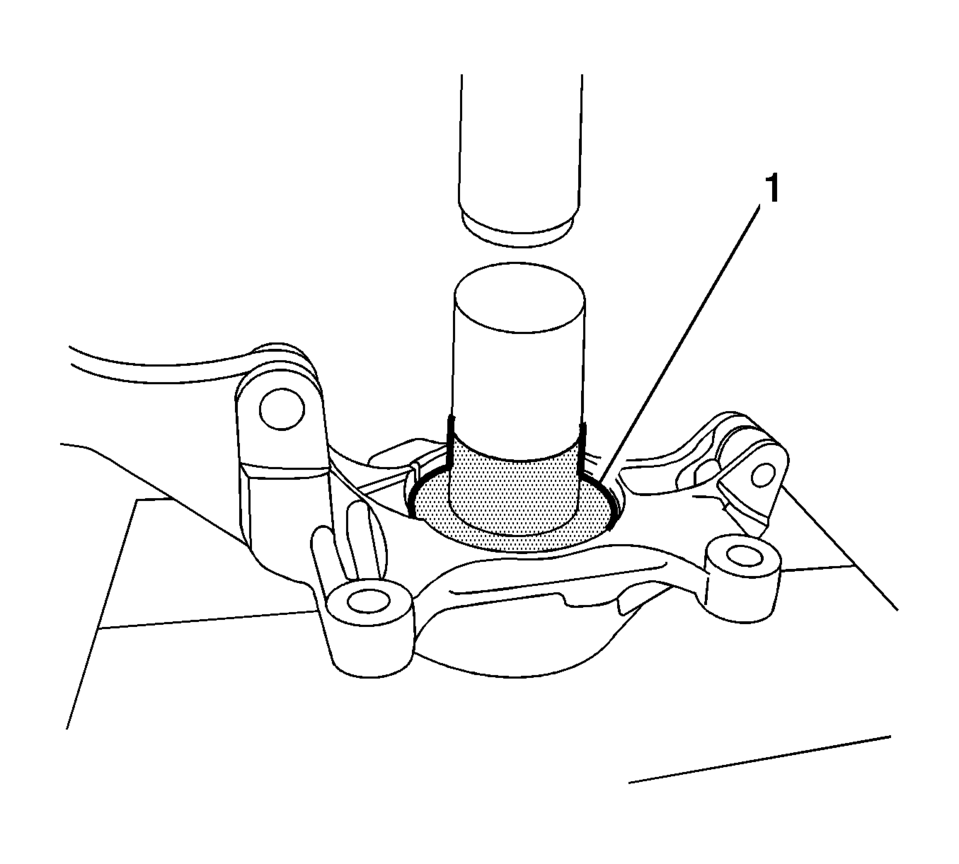
- Using the appropriate tool, remove the retaining ring (1) from the steering knuckle.
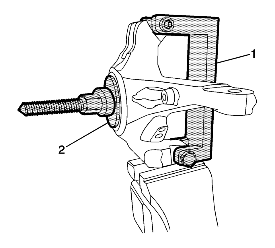
- Position the CH-50559-1 wheel hub/bearing removal/installation bridge assembly (1) and the CH-50559-3 wheel bearing removal adapter (2) on the steering knuckle.
- Remove the wheel bearing from the steering knuckle and discard it. Inspect the bore of the of the steering knuckle for pitting, scoring wear, or corrosion. If damage cannot be easily cleaned up with light sanding, replace the steering knuckle.
- Installation Procedure
-
- The bearing must be installed with the rubber seal facing inboard.
- Ensure that the wheel bearing is evenly seated in the steering knuckle.
- Using the CH-50559-4 wheel hub/bearing installation adapter (1) and the appropriate extension and press, install the new bearing into the steering knuckle until it is correctly seated.
- Position the CH-50559-4 (1) wheel hub/bearing installation adapter and the appropriate extension to the inside of the bearing and position the CH-50559-2 wheel hub removal/installation adapter and the appropriate extension on the wheel hub.
- Press in the hub until it is correctly seated.
- Using the appropriate tool, install the retaining ring (1).
- Verify the hub rotates smoothly.
- Install the steering knuckle assembly in the vehicle. Refer to Steering Knuckle Replacement.
- Lower the vehicle.
Note:
 Rear Wheel Bearing and Hub Replacement (Drum Brake)
Rear Wheel Bearing and Hub Replacement
Callout
Component Name
Preliminary Procedures
Raise and support the vehicle. Refer to Liftin ...
 Hub/Axle Flange and Wheel Stud Runout Inspection
Special Tools
GE-8001 Dial Indicator Set , or equivalent
Raise and support the vehicle. Refer to Lifting and Jacking the Vehicle.
Mark the location of the wheels to the wheel studs and mar ...
Other materials:
Hydraulic Brake System Bleeding (Pressure)
Special Tools
CH-29532 Diaphragm Type Brake Pressure Bleeder
CH-35589-A Brake Pressure Bleeder Adapter
Warning: Refer to Brake Fluid Irritant Warning.
Caution: Refer to Brake Fluid Effects on Paint and Electrical Components
Caution.
Place a clean shop cloth beneath the b ...
Input Shaft Assemble
Special Tools
J-840733 Driver
For equivalent regional tools, refer to Special Tools.
Note: Ensure the input shaft rear bearing retaining ring (2) is
placed on the input shaft before installing the input shaft rear bearing
assembly (1).
Place the input sh ...
Intelligent Key operating range
The Nissan Armada Intelligent Key system functions only when the key is located
within the defined operating range of the request switches 1 and 2 (if equipped).
For optimal performance, the Nissan Armada Intelligent Key must be within approximately
80 cm (31.50 in) of each request switch.
...

0.0054