Chevrolet Sonic Repair Manual: Input Speed Sensor Replacement
- Removal Procedure
-
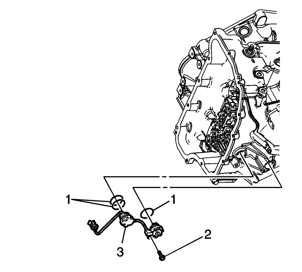
- Remove the control solenoid valve and transmission control module assembly. Refer to Control Solenoid Valve and Transmission Control Module Assembly Replacement.
- Remove the input speed sensor bolt (2) M6 x 23.
- Unlock the 2 retaining tabs inside the transmission housing.
- Remove the input speed sensor (3).
- Remove the 3 input speed sensor seals (1).
- Installation Procedure
-
- Install the 3 input speed sensor seals (1).
- Install the input speed sensor (3).
- Verify that the retaining tabs are locked completely.
- Install the input speed sensor bolt (2) M6 x 23 and tighten to 9 Y (80 lb in)
.
- Install the control solenoid valve and transmission control module assembly. Refer to Control Solenoid Valve and Transmission Control Module Assembly Replacement.
- Perform the transmission adaptive values learn procedure. Refer to Transmission Adaptive Values Learn.
Caution:
Refer to Fastener Caution.
 Front Wheel Speed Sensor Replacement
Removal Procedure
Warning: Refer to Brake Dust Warning.
Raise and support the vehicle. Refer to Lifting and Jacking the Vehicle.
Remove the tire and wheel assembly. Refer ...
 Input and Output Speed Sensor Installation
Input and Output Speed Sensor Installation
Callout
Component Name
1
Input Speed Sensor Assembly Seals
2 ...
Other materials:
Antilock Brake System (ABS) Warning Light
This light comes on briefly when the engine is started.
If the light stays on, turn the ignition to LOCK/OFF or if the light comes on,
stop as soon as possible and turn the ignition off. Then start the engine again
to reset the system. If the light still stays on, or comes on again while driv ...
Exterior Lamp Controls
The exterior lamp control is on the instrument panel to the outboard side of
the steering column.
There are four positions:
(Off): Briefly turn to this position
to turn the automatic light control off or on again.
AUTO (Automatic): Turns the headlamps on automatically at normal brightness, ...
Basic information
WARNING
Incorrect use of the Nissan Armada AEB with Pedestrian Detection system can
lead to serious injury or fatal accidents.
The Nissan Armada AEB system is designed as an additional safety feature
and does not replace attentive and responsible driving. The driver must always
remain a ...

0.0064