Chevrolet Sonic Repair Manual: Instrument Panel Tie Bar Replacement
- Removal Procedure
-
- Remove the Instrument panel assembly. Refer to Instrument Panel Assembly Replacement.
- Remove the steering column and wheel from the vehicle. Refer to Steering Column Replacement.
- Remove the air inlet grill panel. Refer to Air Inlet Grille Panel Replacement.
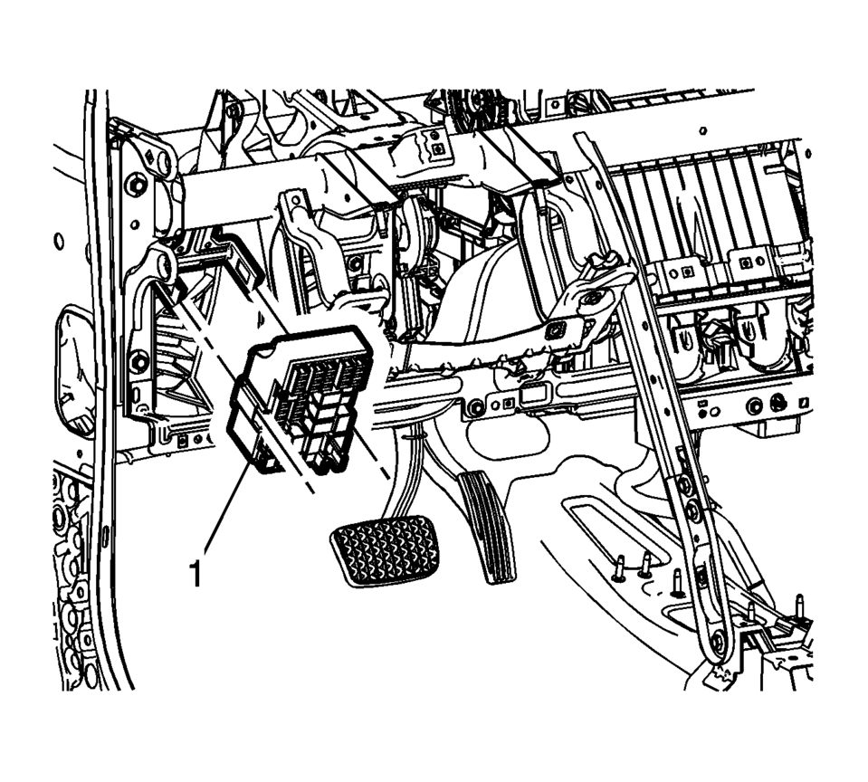
- Unsnap the instrument panel fuse block (1) from the instrument panel tie bar assembly and position out of the way.
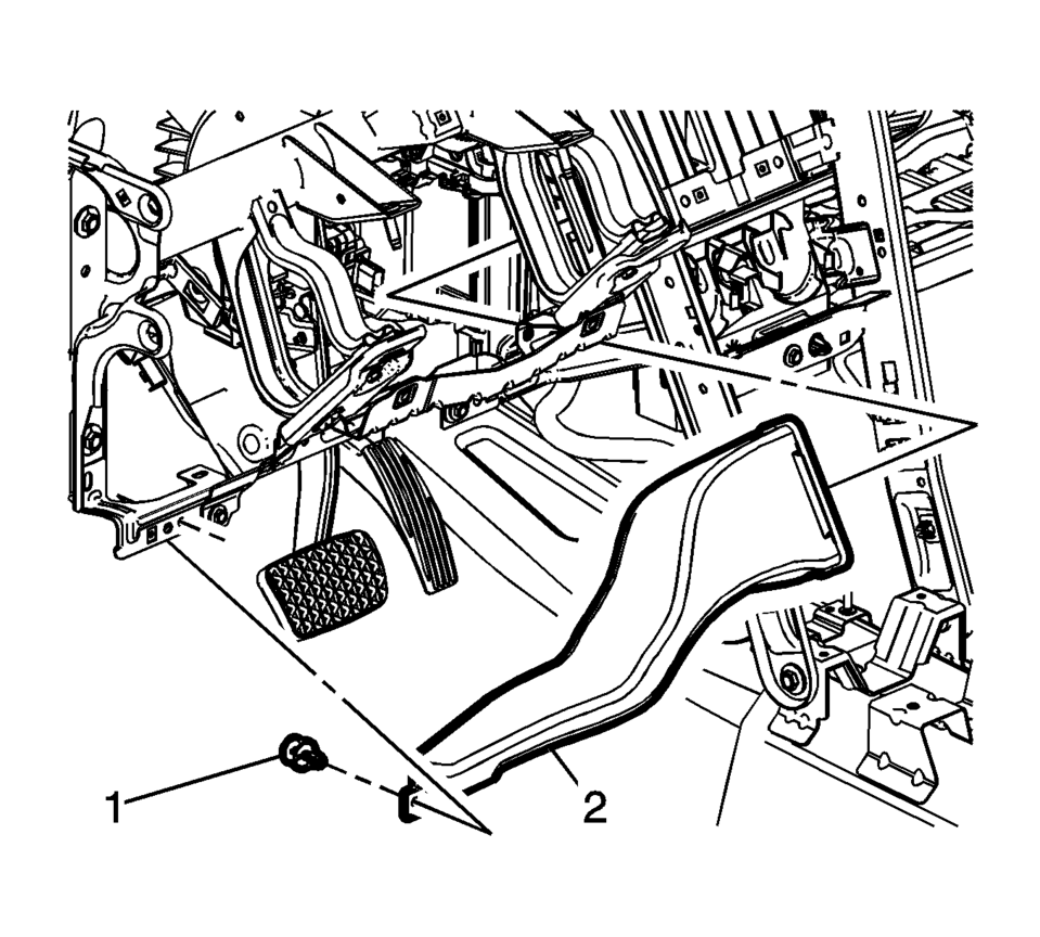
- Remove the push-pin fastener (1) securing the left floor air outlet duct (2) to the instrument panel tie bar assembly.
- Remove the left floor air outlet duct (2) from the vehicle.
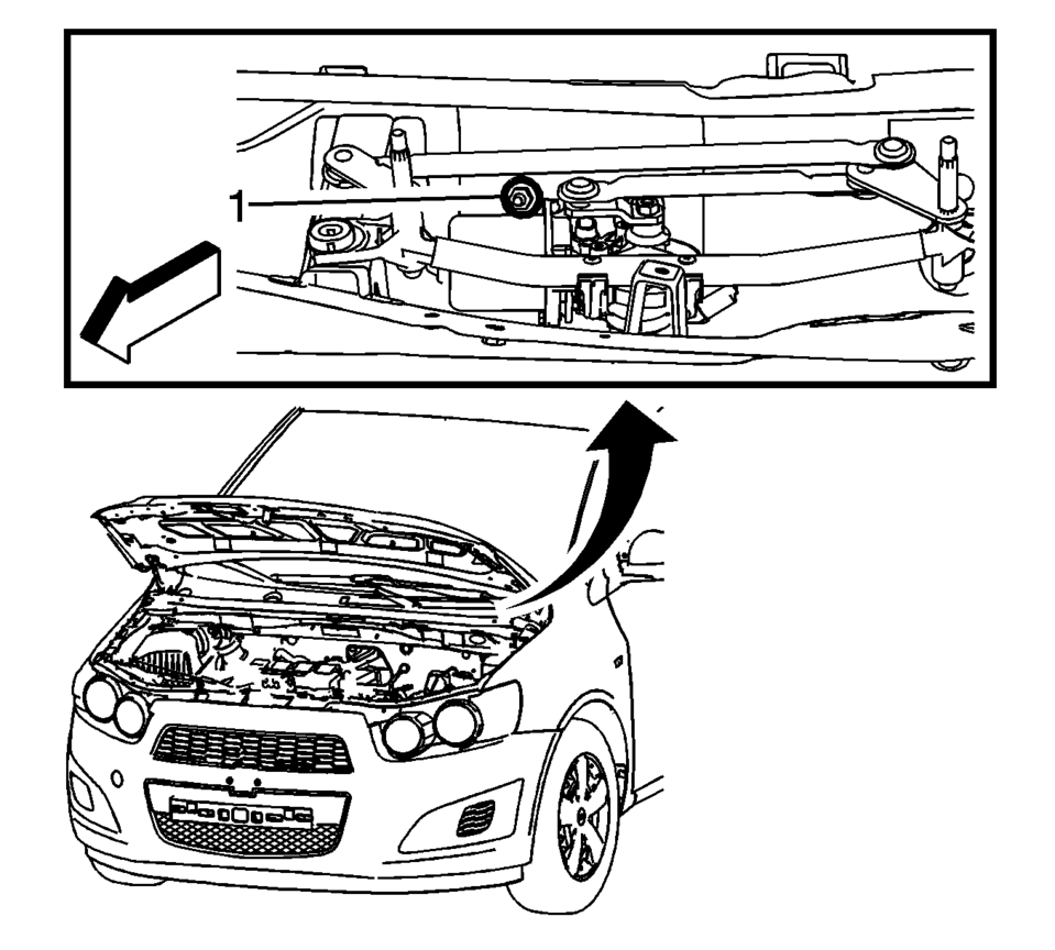
- Remove the nut (1) securing the instrument panel tie bar assembly to the cowl panel.
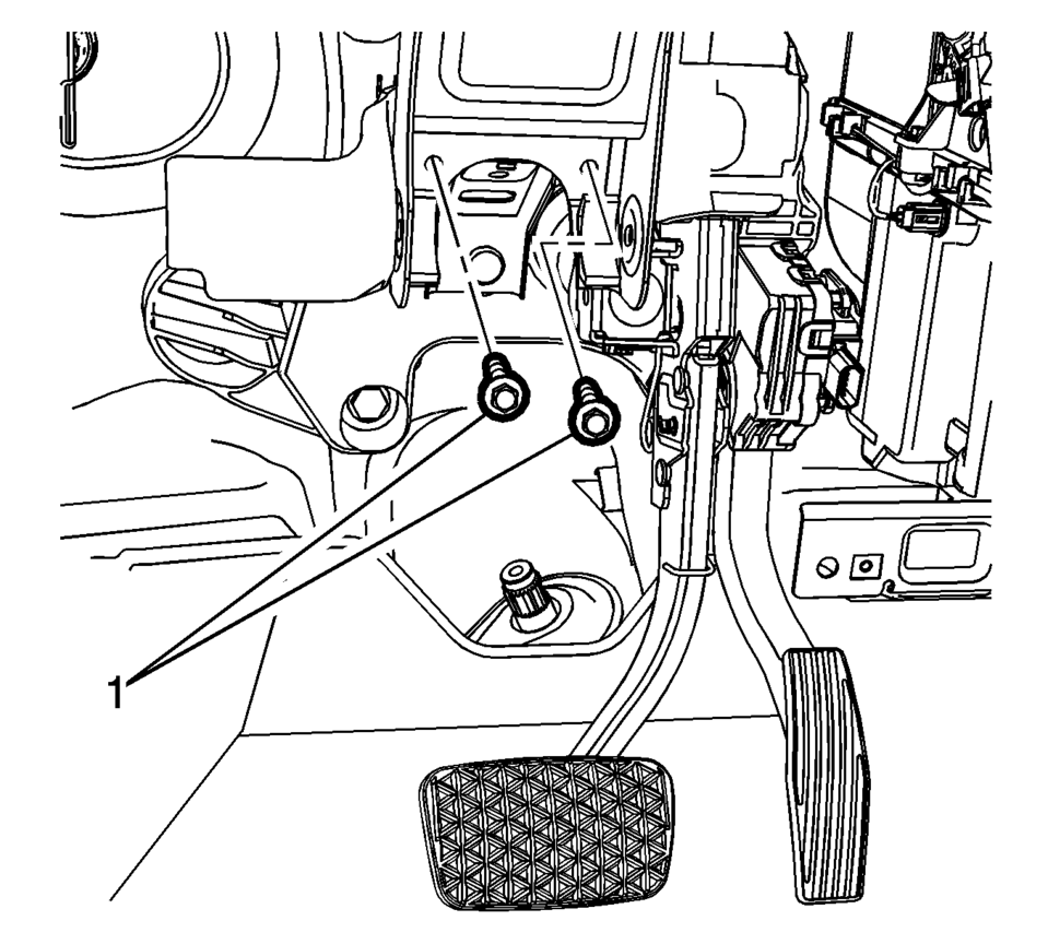
- Remove the bolts (1) securing the instrument panel tie bar assembly to the brake pedal bracket.
- Remove the brake pedal release bracket bolts (1) securing the instrument panel tie bar to the brake pedal mounting bracket.
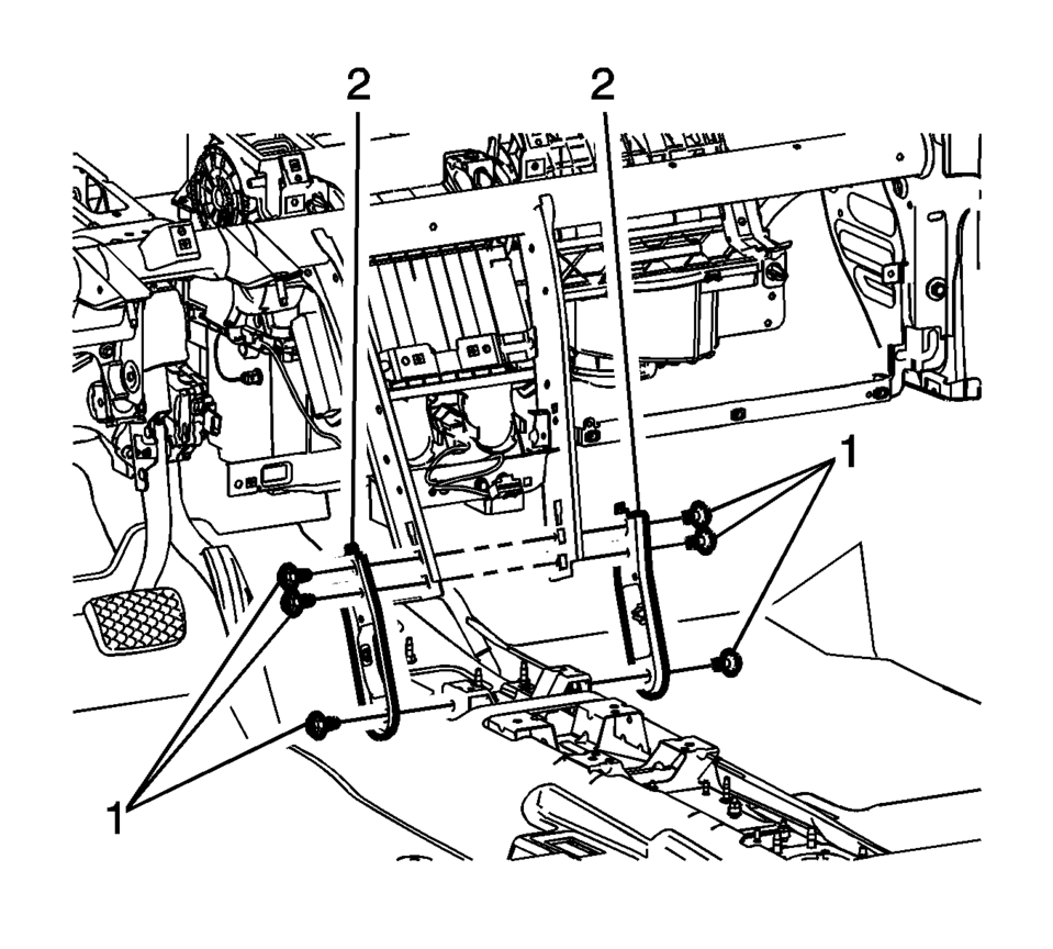
- Remove the bolts (1) securing the right and left instrument panel tie bar lower support brackets (2) to the front floor tunnel panel.
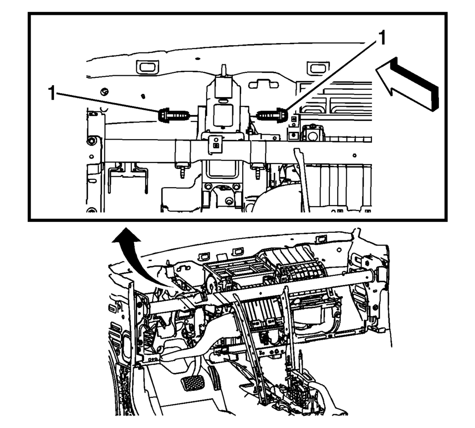
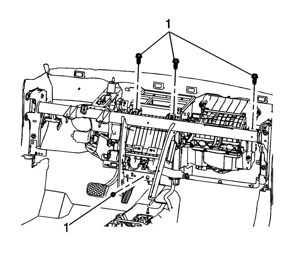
- Remove the fasteners (1) securing the instrument panel tie bar assembly to the HVAC module.
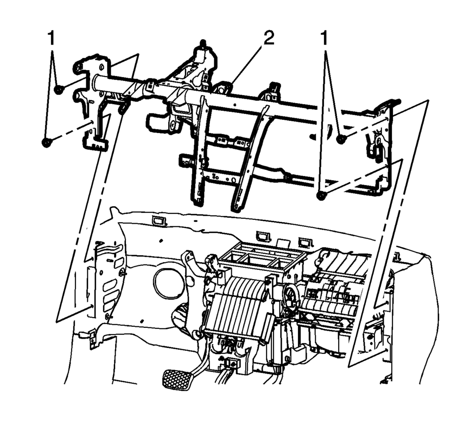
- Remove the bolts (1) securing the instrument panel tie bar assembly to the vehicle body.
- Note the location and routing of the instrument panel wiring harness in order to ensure proper installation.
- With the aid of an assistant remove the instrument panel tie bar assembly from the vehicle.
Note:
Support the HVAC Module in order to prevent damage.
- Installation Procedure
-
- With the aid of an assistant position the instrument panel tie bar assembly into the vehicle.
- Install the instrument panel wiring harness assembly to its in vehicle position as it was noted in the removal procedure.
- Loosely install the bolts (1) securing the instrument panel tie bar assembly to the vehicle body.
- Loosely install the fasteners (1) securing the instrument panel tie bar assembly to the HVAC module.
- Remove the support from the HVAC module.
- Loosely install the bolts (1) securing the right and left instrument panel tie bar lower support brackets (2) to the front floor tunnel panel.
- Loosely install the brake pedal release bracket bolts (1) securing the instrument panel tie bar to the brake pedal mounting bracket.
- Loosely install the bolts (1) securing the instrument panel tie bar assembly to the brake pedal bracket.
- Loosely install the nut (1) securing the instrument panel tie bar assembly to the cowl panel.
- Tighten the instrument panel tie bar to vehicle body bolts to 22Y (16 lb ft).
- Tighten the instrument panel tie bar to HVAC module fasteners to
9Y (80 lb in).
- Tighten the instrument panel tie bar lower support bracket to front
floor tunnel panel bolts to 22Y (16 lb ft).
- Tighten the instrument panel tie bar to the brake pedal release bracket
bolt to 22Y (16 lb ft).
- Tighten the instrument panel tie bar assembly to the brake pedal bracket
bolts to 9Y (80 lb in).
- Tighten the instrument panel tie bar assembly to the cowl panel nut
to 22Y (16 lb ft).
- Install the left floor air outlet duct (2) into the vehicle.
- Install the push-pin fastener (1) securing the left floor air outlet duct (2) to the instrument panel tie bar assembly.
- Snap the instrument panel fuse block (1) onto the instrument panel tie bar assembly.
- Install the air inlet grill panel. Refer to Air Inlet Grille Panel Replacement.
- Install the steering column and wheel from the vehicle. Refer to Steering Column Replacement.
- Install the Instrument panel assembly. Refer to Instrument Panel Assembly Replacement.
Caution:
Refer to Fastener Caution.
 Front End Upper Tie Bar Replacement
Front End Upper Tie Bar Replacement
Callout
Component Name
Preliminary Procedures
Disable the SIR system. Refer to SIR Disabling an ...
 Steering Linkage Inner Tie Rod Inspection
Special Tools
GE-8001 Dial Indicator Set
For equivalent regional tools, refer to Special Tools.
Note: This inspection procedure does not supersede local government
required inspection ...
Other materials:
Headlining Trim Panel Replacement (Hatchback without Sunroof)
Headlining Trim Panel Replacement
Callout
Component Name
Warning: Do not attempt to repair or alter the head impact
energy-absorbing material glued to the headliner or to the garnish trims.
If the material is damaged ...
Evaporative Emission Canister Replacement
Removal Procedure
Raise and support the vehicle. Refer to Lifting and Jacking the Vehicle.
Remove the EVAP canister cover fasteners (1) and cover (2).
Warning: Do not breathe the air through the EVAP component
tubes or hoses. The fuel vapors inside t ...
Rear-facing child restraint installation using LATCH
Before installing a child restraint in the Nissan Armada, carefully review all
warnings and precautions provided in the "Child safety" and "Child restraints" sections
of this manual.
Do not use the LATCH lower anchors if the combined weight of the child and the
child restr ...

0.0059