Chevrolet Sonic Repair Manual: Parking Brake Adjustment (Disc Brake)
Note:
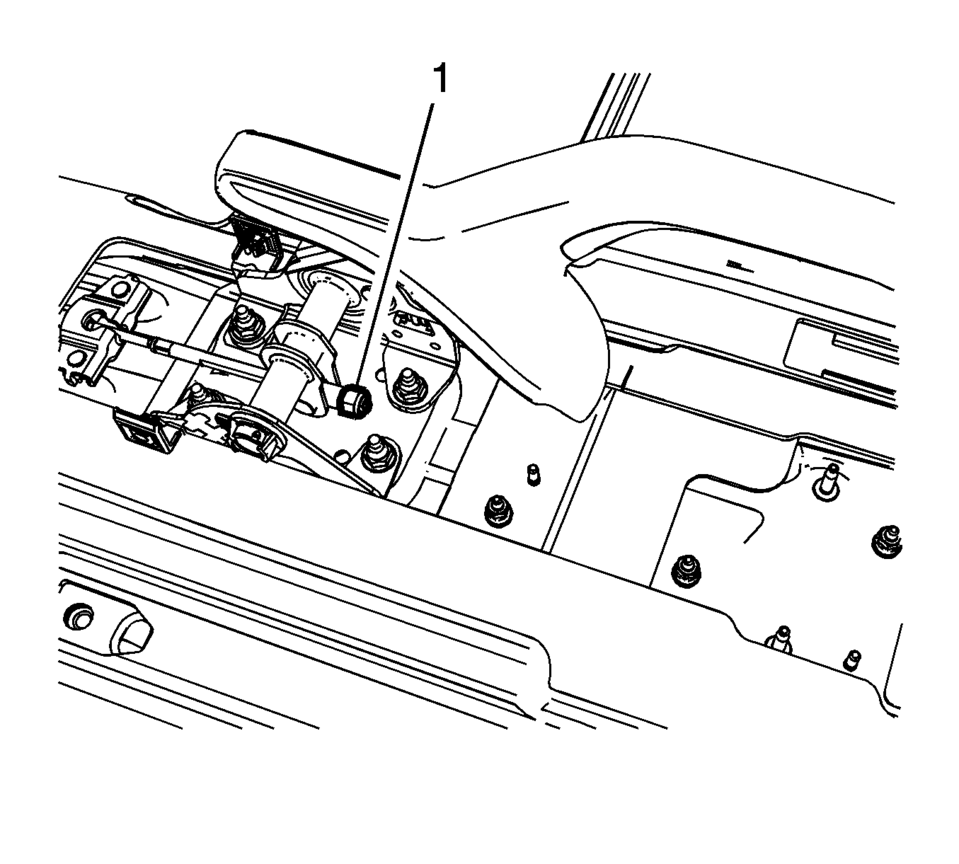
The park brake cable adjusting nut is a nylon lock type. Use ONLY HAND TOOLS whenever tightening or loosening the adjusting nut.
- Apply and fully release the park brake several times. Verify that the park brake lever releases completely.
- Turn ON the ignition. Verify the red BRAKE warning lamp is not illuminated.
- If the red BRAKE warning lamp is illuminated, verify the following:
- The park brake lever is in the fully released position and against the stop.
- There is no slack in the park brake cables.
- One of the tire and wheel assemblies should not rotate forward or rearward.
- The other tire and wheel assembly should not rotate forward or rearward, or should require substantial effort to rotate.
 Park Brake and P (Park) Mechanism Check
Warning: When you are doing this check, the vehicle could begin to
move. You or others could be injured and property could be damaged. Make sure
there is room in front of the vehicle in case ...
 Parking Brake Adjustment (Drum Brake)
Note: The park brake cable adjusting nut is a nylon lock type. Use
ONLY HAND TOOLS whenever tightening or loosening the adjusting nut.
Apply and fully release the park brake several times ...
Other materials:
Intake Camshaft Removal
Remove the camshaft bearing cap bolts in a spiral sequence as shown one
turn at a time until there is no spring tension pushing on the camshaft.
Note: Mind the markings on the camshaft bearing caps to ensure
they will be installed in the same position.
Remove the ...
Timing Belt Upper Front Cover Installation
Install the timing belt upper front cover (1).
Caution: Refer to Fastener Caution.
Install the 2 timing belt upper front cover bolts (2) and tighten to
6 Y(53 lb in).
...
Control Valve Body Assembly Disassemble (Gen 1)
Control Valve Body Assembly Disassemble
Callout
Component Name
1
Control Solenoid Valve Support
2
Control Valve Body Bolt M5 x 40.5 (Qty: 1)
3
...

0.0071