Chevrolet Sonic Repair Manual: Piston and Connecting Rod Assemble
Special Tools
EN-49941 Remover / Installer Piston Retainer Ring
For equivalent regional tools, refer to Special Tools.
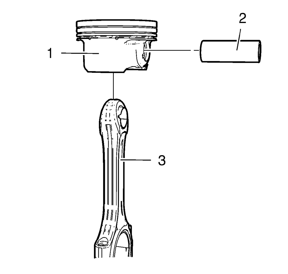
- Install the connecting rod (3) and the piston pin (2) to the piston (1).
- Install the piston and connecting rod assembly to a bench vise. Use aluminium braces.
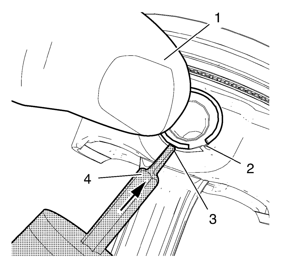
- Place the piston pin retainer in the piston pin retainer groove so that the ring gap lays on the notch (2).
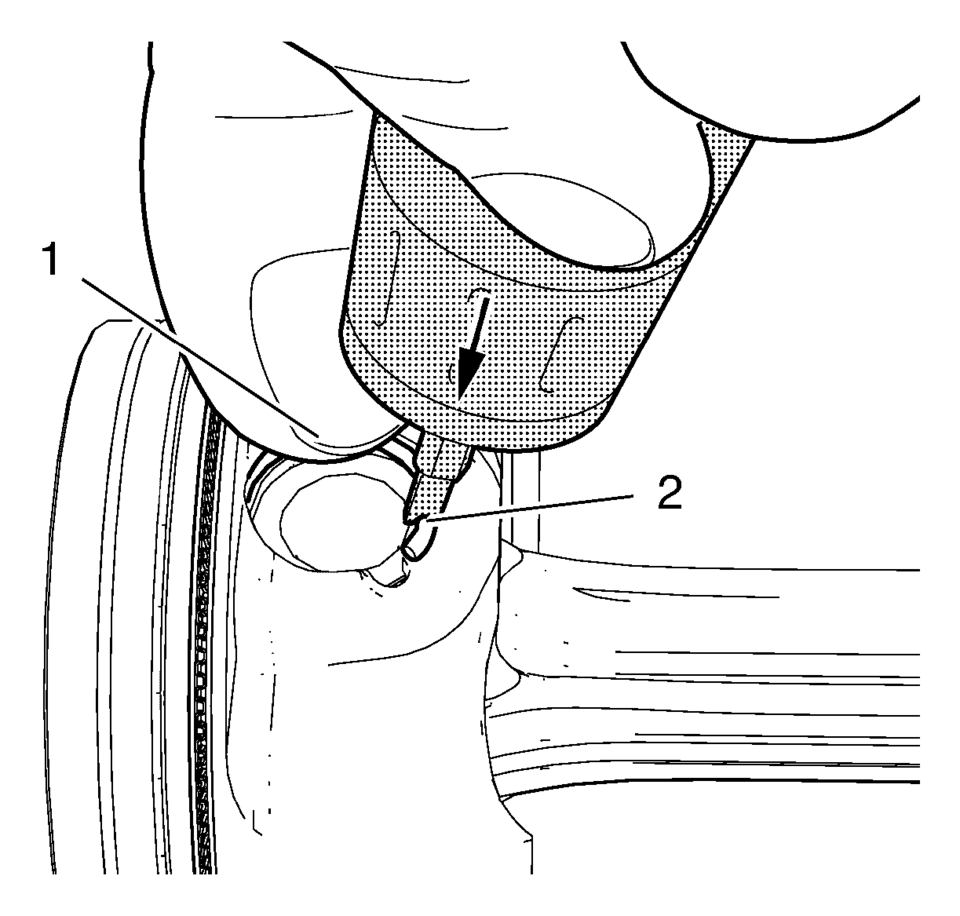
- Push the piston pin retainer down with the thumb in the shown position (1) and hold.
- Apply the EN-49941 installer (4) to the piston pin retainer in the position shown (3) and push in direction of the arrow while pushing down with the thumb.
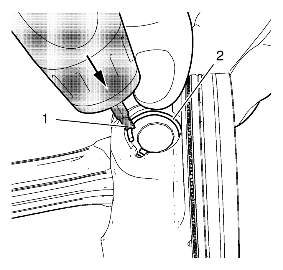
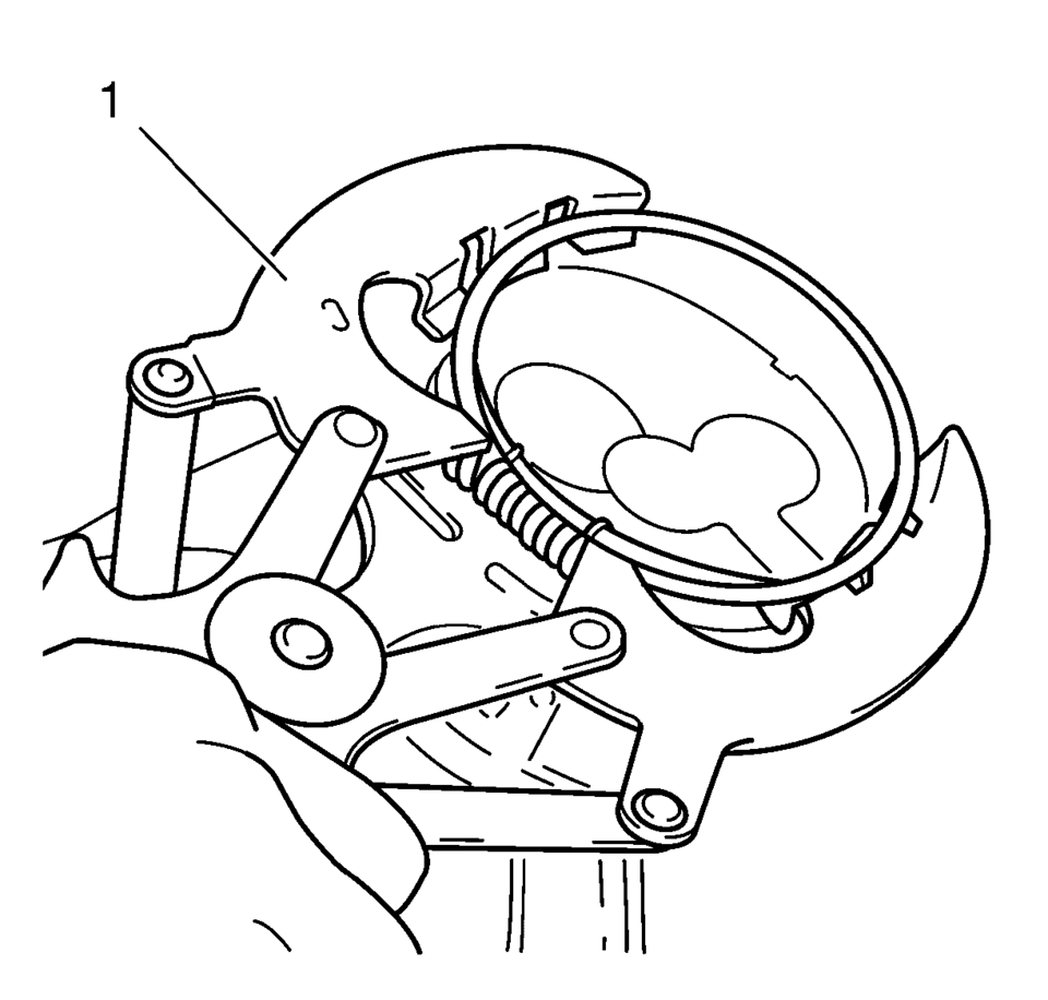
- Move the EN-49941 installer (1) carefully to the position shown while pushing in direction of the arrow until the piston pin retainer engages in the piston pin retainer groove.
- Push down the piston ring retainer to get a proper seat in the groove.
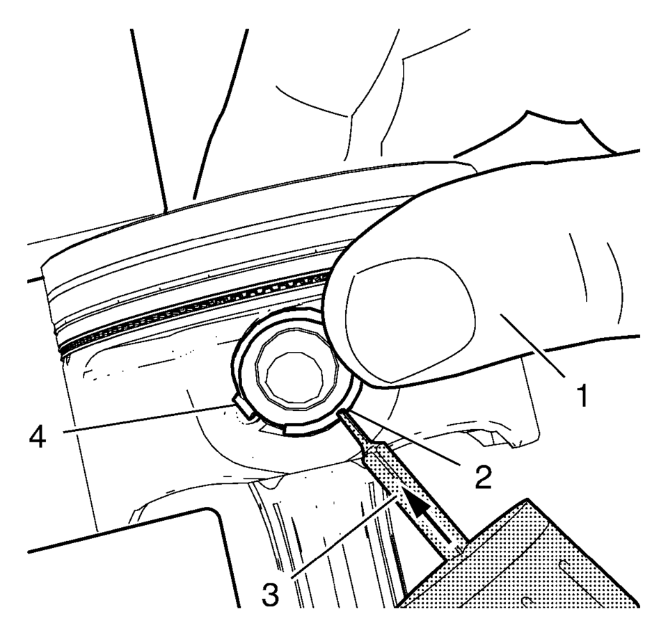
- Place the piston pin retainer in the piston pin retainer groove so that the ring gap lays on the notch (4).
- Push the piston pin retainer down with the thumb in the position shown (1) and hold.
- Apply the EN-49941 installer (3) to the piston pin retainer in the position shown (2) and push in direction of the arrow while pushing down with the thumb.
- Move the EN-49941 installer (2) carefully to the position shown while pushing in direction of the arrow until the piston pin retainer engages in the piston pin retainer groove.
- Push down the piston ring retainer to get a proper seat in the groove.
- Remove the piston and connecting rod assembly from the bench vise.
- Install the piston rings. Use piston ring pliers (1).
- The piston rings must be ordered as followed:
Note:
Lubricate the piston pin with clean engine oil.
Warning:
Use extreme care when removing snap rings. Always wear adequate eye protection in order to avoid personal injury.
Warning:
Use care when removing or installing the piston retainer ring. Ensure the EN-49941 remover/installer is installed properly onto the retainer ring and that hands and fingers are kept clear from the front of the tool. Otherwise, bodily injury may occur.
Note:
Notch (2) on right side.
Note:
The EN-49941 installer should be applied in a perpendicular position to the piston pin retainer.
Note:
Push the piston pin retainer down in the position shown (2).
Note:
Notch (4) on left side. EN-49941 installer should be used with left hand.
Note:
The EN-49941 installer should be applied in a perpendicular position to the piston pin retainer.
Note:
Push the piston pin retainer down in the position shown (1).
Note:
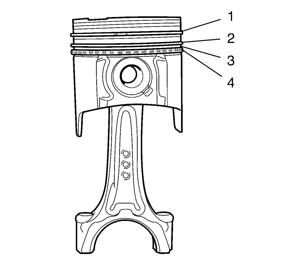
Mind the TOP marking on the piston rings.
- Upper compression ring (1)
- Lower compression ring (2)
- Piston oil ring with spacer (3), (4)
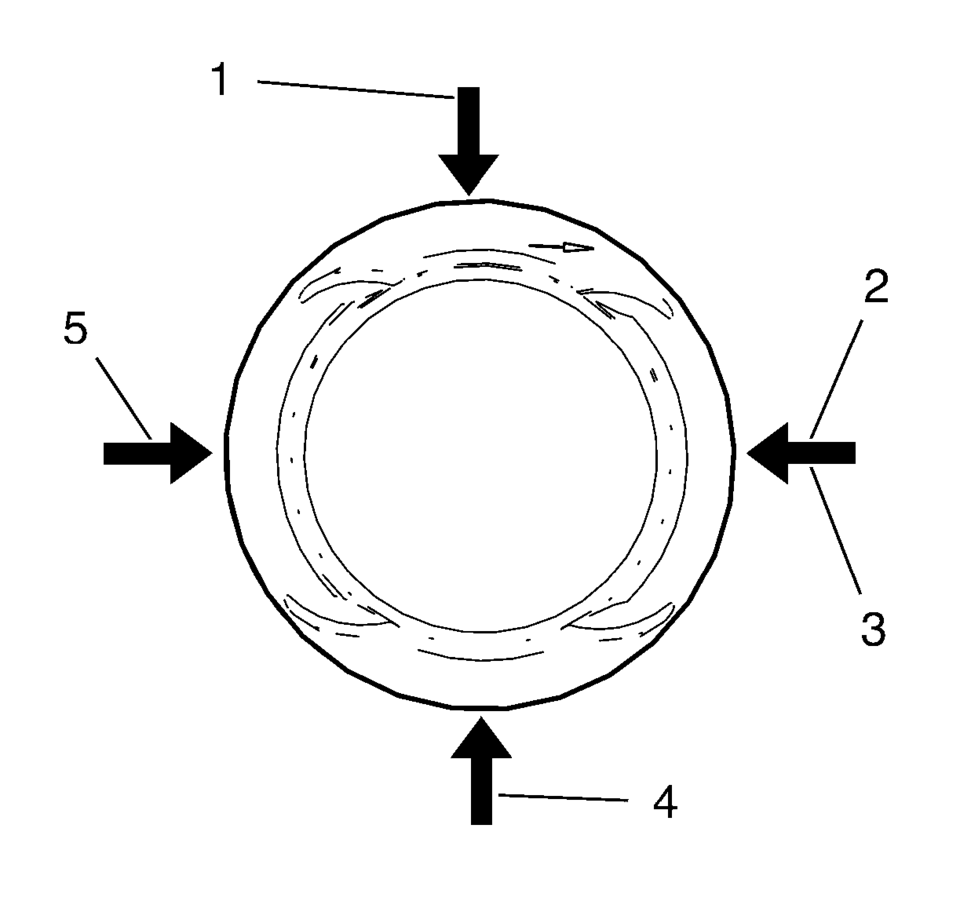
- Upper compression ring joint (2)
- Lower compression ring joint (5)
- Oil ring joint, upper part (1)
- Oil ring joint, lower part (4)
- Oil ring spacer joint (3)
 Engine Front Cover with Oil Pump Replacement
Removal Procedure
Disconnect the battery negative cable. Refer to Battery Negative Cable
Disconnection and Connection.
Set the engine to TDC. Refer to Camshaft Timing Chain Inspec ...
 Piston and Connecting Rod Disassemble
Remove the piston with connection rod. Refer to Piston, Connecting Rod,
and Bearing Removal.
Note: Note installation position of the piston in respect of the
connection rod.
...
Other materials:
Rear License Plate Lamp Bulb Replacement (Hatchback)
Rear License Plate Lamp Bulb Replacement
Callout
Component Name
Preliminary Procedure
Remove the rear license plate lamp housing. Refer to Rear License Plate
Lamp Replacement.
1
License Plate La ...
Replacing Safety Belt System Parts after a Crash
Warning: A crash can damage the safety belt system in the vehicle.
A damaged safety belt system may not properly protect the person using it, resulting
in serious injury or even death in a crash. To help make sure the safety belt
systems are working properly after a crash, have them insp ...
Vehicle Speed Sensor Replacement
Vehicle Speed Sensor Replacement
Callout
Component Name
1
Engine Wiring Harness Bracket Nut
Caution: Refer to Fastener Caution.
Tighten
9 Y (80 lb in)
2
...

0.0096