Chevrolet Sonic Repair Manual: Piston, Connecting Rod, and Bearing Removal
- Install the crankshaft balancer bolt.
- Set the pistons 1 and 4 to TDC in direction of engine rotation.
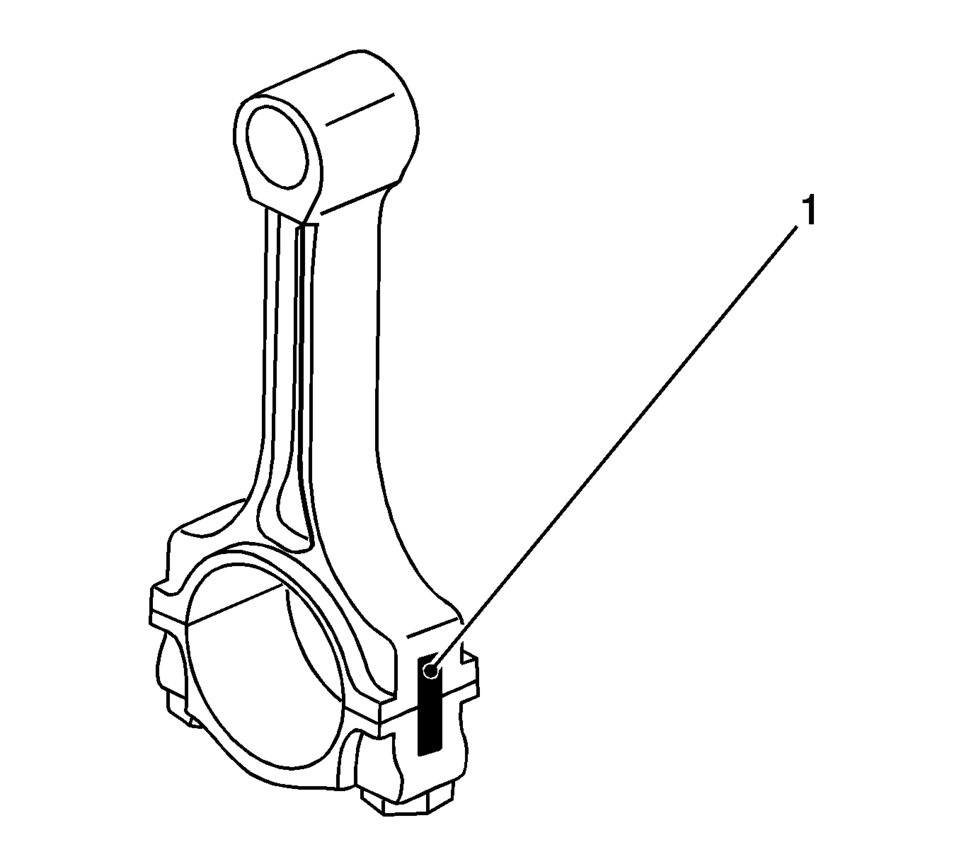
- Mark the connecting rod with the connecting rod bearing cover (1).
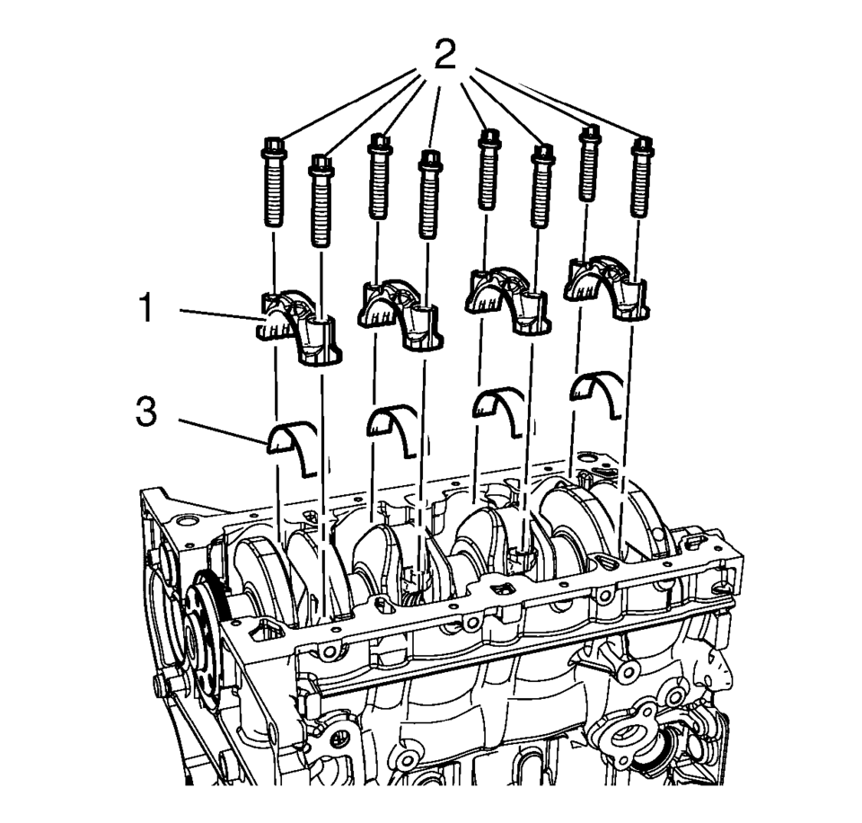
- Remove the 4 connecting rod bearing caps bolts (2) of cylinder 1 and 4.
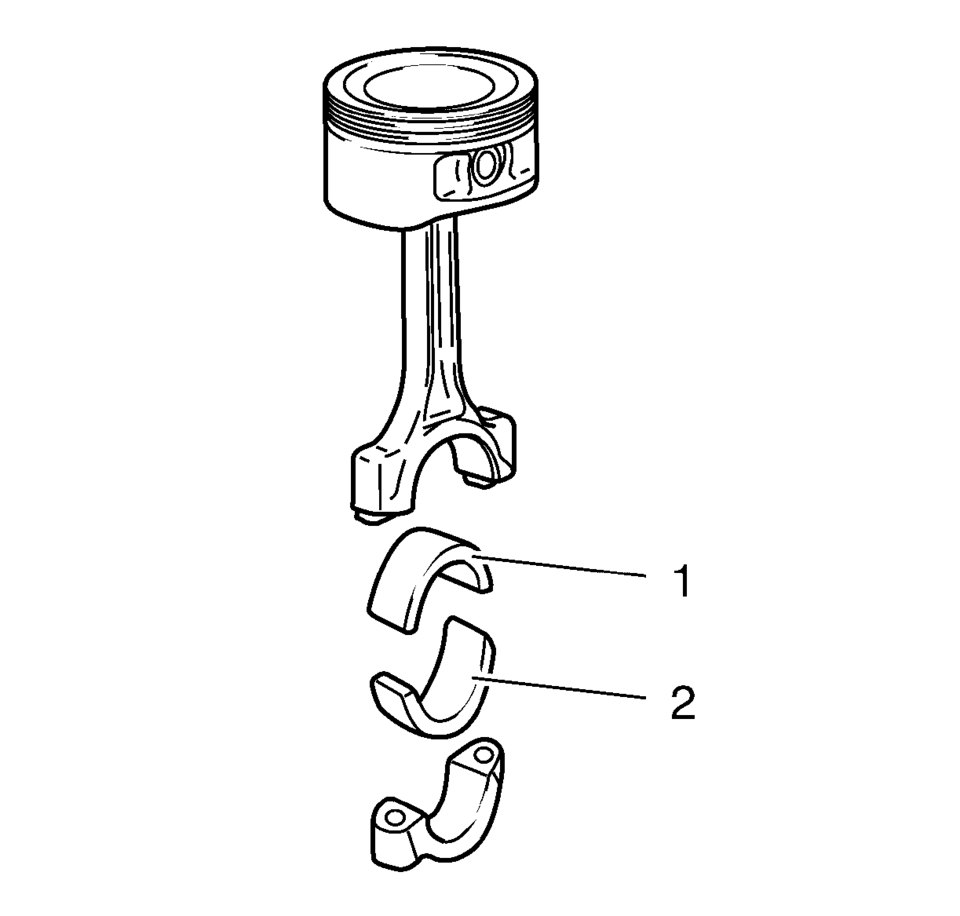
- Remove the connecting rod bearing caps (1) and the connecting rod bearing (3).
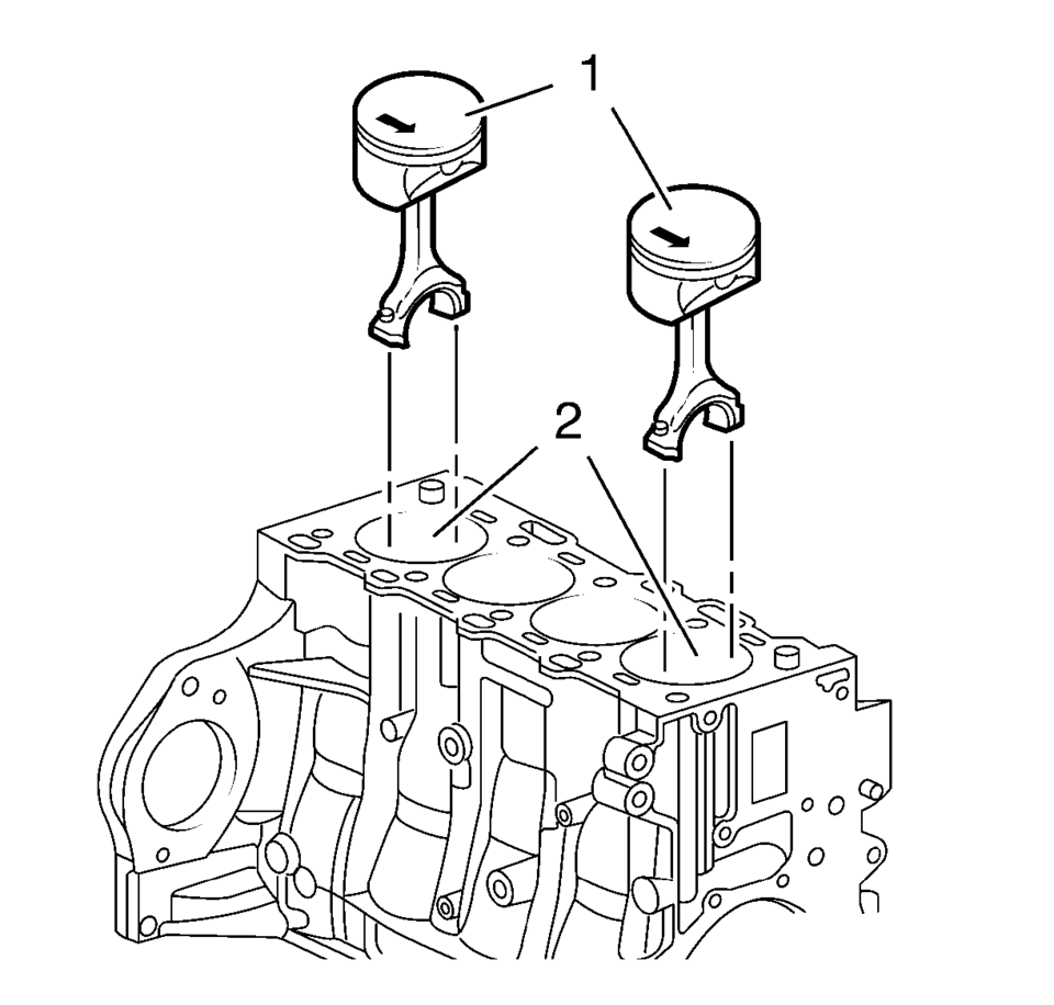
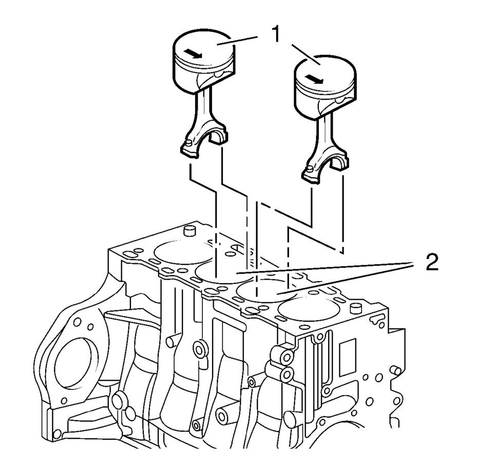
- Push the pistons 1 and 4 (1) out of the cylinder bore (2).
- Remove the pistons 1 and 4 (1).
- Turn crankshaft on crankshaft balancer through 180┬░ in direction of rotation of engine.
- Mark the connecting rod with the connecting rod bearing cover (1).
- Remove the 4 connecting rod bearing caps bolts (2) of cylinder 2 and 3.
- Remove the connecting rod bearing caps (1) and the connecting rod bearing (3).
- Push the pistons 2 and 3 (1) out of the cylinder bore (2).
- Remove the pistons 2 and 3 (1).
- Remove the connecting rod bearing (1, 2).
- Check the components. Refer to Piston, Connecting Rod, and Bearing Cleaning and Inspection.
Note:
Note cylinder sequence.
Note:
The shear surfaces of the con-rod and the con-rod bearing cover form a unique fit and must not be swapped or damaged. Do not lay down on the shear surfaces.
Note:
Note cylinder sequence.
Note:
The shear surfaces of the con-rod and the con-rod bearing cover form a unique fit and must not be swapped or damaged. Do not lay down on the shear surfaces.
Note:
Observe correct fitting position, observe alignment.
 Piston, Connecting Rod, and Bearing Installation
Special Tools
EN-470-B Angular Torque Wrench
For equivalent regional tools, refer to Special Tools.
Adjust the piston ring joints as follows:
Upper compression ring (1).
...
 2-6 Clutch Piston Installation (6T30)
2-6 Clutch Piston Installation
Callout
Component Name
1
2?E Clutch Piston Assembly
Note:
Position the ...
Other materials:
Conference Calling
Conference calling and three-way calling must be supported on the Bluetooth phone
and enabled by the wireless service carrier to work.
To start a conference while in a current call:
1. Turn or press the Push/MENU/ TUNE knob.
2. Select Enter Number.
3. Enter the character sequence then select C ...
Rear Seat Head Restraint Guide Replacement
Rear Seat Head Restraint Guide Replacement
Callout
Component Name
Preliminary Procedure
Remove the rear seat head restraint. Refer to Rear Seat Head Restraint
Replacement
1
Rear Seat Head Restra ...
Driving safety precautions
Your Nissan Armada is engineered to deliver confident performance both on paved
roads and in light off-road conditions. However, it is important to understand that
the Nissan Armada is primarily designed for recreational and everyday driving, and
not for extreme off-road environments. Avoid dr ...

0.01