Chevrolet Sonic Owner's Manual: Rear Safety Belt Comfort Guides
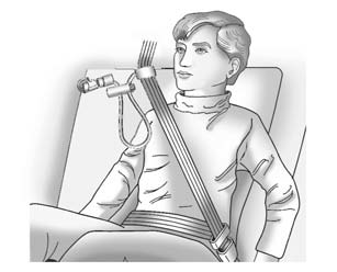
Rear safety belt comfort guides may provide added safety belt comfort for older children who have outgrown booster seats and for some adults. When installed on a shoulder belt, the comfort guide positions the shoulder belt away from the neck and head.
Safety belt comfort guides are available through your dealer.

To install the adjustable comfort guide to the seatback and the safety belt:

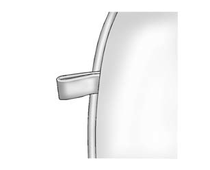
1. Locate the anchor loop on the rear outboard seatback, near the top.
2. Attach the adjustable comfort guide to the anchor loop by threading the hook through the loop.

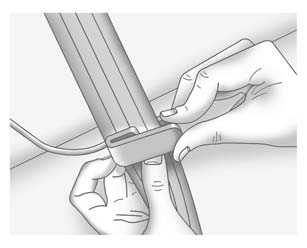
3. Place the guide over the belt, and insert the two edges of the belt into the slots of the guide.

4. Be sure that the belt is not twisted and it lies flat. The elastic cord must be under the belt and the guide on top.
5. The elastic cord on the comfort guide is adjustable. You can make it longer or shorter by squeezing both ends of the plastic adjuster and pulling on the elastic cord or the guide.
6. Adjust the guide so the shoulder portion of the belt is on the shoulder and not falling off of it. The belt should be close to, but not contacting, the neck. Improper comfort guide adjustment could reduce the effectiveness of the safety belt in a crash.
Warning
A safety belt that is not properly worn may not provide the protection needed in a crash. The person wearing the belt could be seriously injured. The shoulder belt should go over the shoulder and across the chest. These parts of the body are best able to take belt restraining forces.

7. Buckle and position the safety belt as described previously in this section. Make sure that the shoulder belt crosses the shoulder.
To remove and store the comfort guide, squeeze the belt edges together so that the safety belt can be removed from the guide. Un-hook the guide from the loop on the seat. Store the guide in a convenient place like the glove box for the next time it is needed.
 Safety Belt Pretensioners
This vehicle has safety belt pretensioners for front outboard occupants. Although
the safety belt pretensioners cannot be seen, they are part of the safety belt assembly.
They can help tighten the ...
 Safety Belt Use During Pregnancy
Safety belts work for everyone, including pregnant women. Like all occupants,
they are more likely to be seriously injured if they do not wear safety belts.
A pregnant woman should wear a lap-sho ...
Other materials:
Remote Keyless Entry (RKE) System
The RKE transmitter may work up to 60m (195 ft) away from the vehicle.
The RKE transmitter can have one of the two symbols for the remote trunk release.
With Remote Start Shown
Press the key release button to extend the key blade. The key can be used for
the ignition and all locks.
Press ...
Hood Replacement
Hood Replacement
Callout
Component Name
Preliminary Procedure
Disconnect the windshield washer nozzle hose.
1
Hood Hinge Nut (Qty:?€‰4)
Caution: Refer to Fastener Caution.
Procedu ...
Transmission Rear Mount Replacement
Removal Procedure
Raise and support the vehicle. Refer to
Lifting and Jacking the Vehicle.
Remove and DISCARD the rear transmission mount bracket
to rear mount through bolt (1).
Remove rear transmission mount to frame bolt (3).
Push and hold ...
0.007
