Chevrolet Sonic Repair Manual: Rear Wheel Speed Sensor Replacement
- Removal Procedure
-
Warning:
Refer to Brake Dust Warning.
- Raise and support the vehicle. Refer to Lifting and Jacking the Vehicle.
- Remove the tire and wheel assembly. Refer to Tire and Wheel Removal and Installation.
- Remove the rear wheel speed sensor harness connector cover nuts (1).
- Remove the rear wheel speed sensor harness connector cover (1).
- Clean the rear drum brake area around the wheel speed sensor of any accumulated dirt and debris.
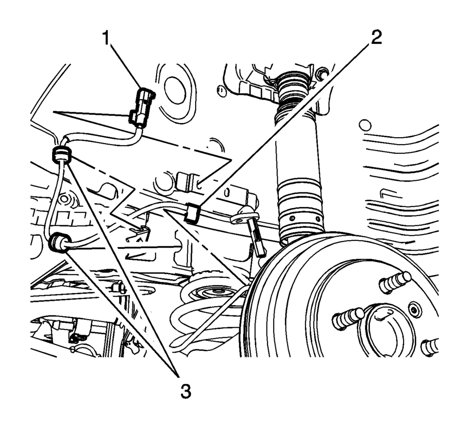
- Disconnect the wheel speed sensor electrical connector (1) and release the connector from the wheelhouse bracket.
- Release the wheel speed sensor harness retainer (2) from the wheel cylinder brake pipe.
- Release the wheel speed sensor harness grommets (3) from the bracket.
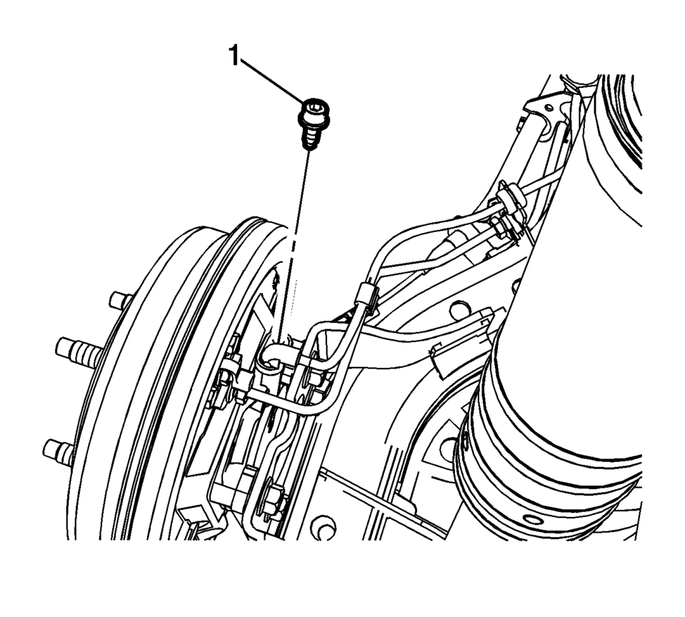
- Remove the wheel speed sensor bolt (1).
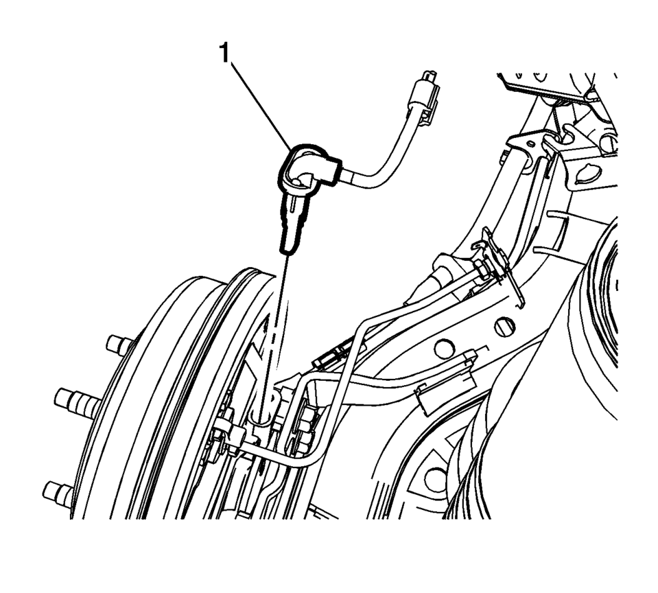
- Remove the wheel speed sensor (1) from the rear drum brake spacer by pulling the sensor straight upward using a slight twisting motion.


- Installation Procedure
-
- Install the wheel speed sensor (1) to the rear drum brake spacer.
- Install the wheel speed sensor bolt (1) and tighten to 8 Y (71 lb in)
.
- Connect the wheel speed sensor electrical connector (1) and install the connector to the wheelhouse bracket.
- Install the wheel speed sensor harness retainer (2) to the wheel cylinder brake pipe.
- Install the wheel speed sensor harness grommets (3) to the bracket.
- Install the rear wheel speed sensor harness connector cover (1).
- Install the rear wheel speed sensor harness connector cover nuts (1)
and tighten to 2 Y (18 lb in)
.
- Install the tire and wheel assembly. Refer to Tire and Wheel Removal and Installation.
- Perform the Diagnostic System Check - Vehicle.
Caution:
Refer to Fastener Caution.
Note:
If the wheel speed sensor grommets are equipped with a molded rib, position the grommets with the rib at the open end of the wheel speed sensor harness brackets. Do not twist the wheel speed sensor harness.
 Output Speed Sensor Replacement
Output Speed Sensor Replacement
Callout
Component Name
Preliminary Procedure
Remove the control valve body. Refer to Control Va ...
 Vehicle Speed Sensor Replacement
Vehicle Speed Sensor Replacement
Callout
Component Name
1
Engine Wiring Harness Bracket Nut
Caution: Refer to Fa ...
Other materials:
Headlamp High/Low-Beam Changer
(Headlamp High/Low-Beam Changer):
Push the turn signal lever away from you to turn the high beams on.
Push the lever again or pull the lever toward you to return to low beams.
This indicator light turns on in the instrument cluster when the high-beam headlamps
are on. ...
Exhaust System Replacement
Removal Procedure
Special Tools
CH-6614 Chain Pipe Cutter
For equivalent regional tools, refer to Special Tools.
Warning: Refer to Protective Goggles and Glove Warning
Warning: Refer to Exhaust Service Warning.
Raise and support the vehicle. Refer to Lifting ...
Maintenance schedules
Basic information
To ensure your Nissan Armada delivers reliable performance, optimal safety, and
long-term efficiency, NISSAN provides two distinct maintenance schedules tailored
to different driving conditions. These schedules are carefully designed to cover
both mileage and time intervals, ...

0.0102