Chevrolet Sonic Repair Manual: Stabilizer Shaft Replacement
- Removal Procedure
-
- Remove the intermediate steering shaft lower bolt. Refer to Intermediate Steering Shaft Replacement.
- Raise and support the vehicle. Refer to Lifting and Jacking the Vehicle.
- Remove the tire and wheel assembly. Refer to Tire and Wheel Removal and Installation.
- Remove the front wheelhouse inner liner front extension. Refer to Front Wheelhouse Liner Inner Front Extension Replacement.
- Remove the front bumper impact bar lower bracket. Refer to Front Bumper Impact Bar Lower Bracket Replacement.
- Remove the stabilizer shaft links from the stabilizer shaft. Refer to Stabilizer Shaft Link Replacement.
- Remove the lower control arm ball joint bolt and nut from the steering knuckle. Refer to Lower Control Arm Replacement.
- Disconnect the steering linkage tie rod end from the steering knuckle. Refer to Steering Linkage Outer Tie Rod Replacement.
- Remove the transmission rear mount to bracket retaining bolt. Refer to Transmission Mount Bracket Replacement - Rear.
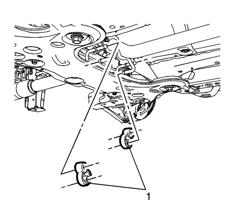
- Remove the exhaust pipe insulators (1).
- Release the front suspension frame front bolts about 10 mm.
- Usingf a suitable support, support the crossmember area of the cradle.
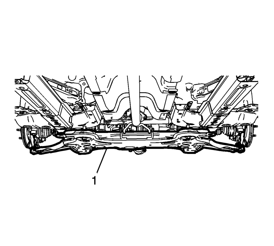
- Using a suitable support, lower the front suspension frame (1) about 500 mm enough to gain access to the stabilizer shaft insulator bolts and to remove the stabilizer shaft. Refer to Drivetrain and Front Suspension Frame Replacement
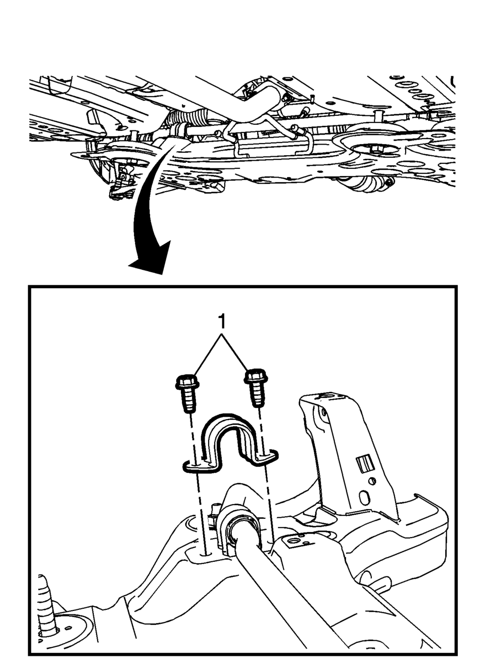
- Remove the stabilizer shaft insulator bolts (1).
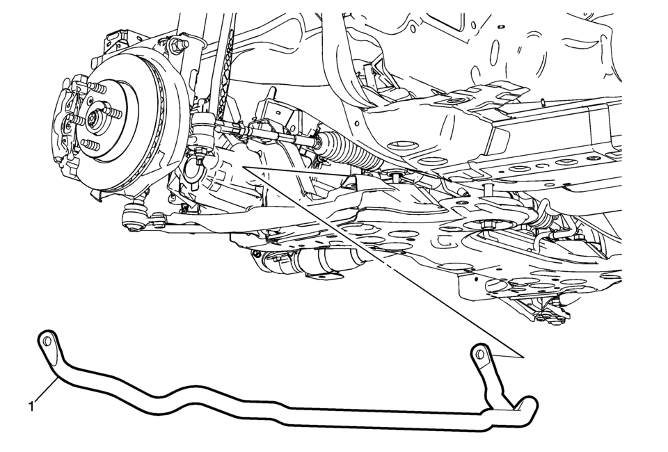
- Remove the front stabilizer shaft (1) from the front suspension frame.
Note:
It is not necessary to remove the front bumper facia in this procedure.
Note:
It maybe necessary to maneuver the front stabilizer shaft in such away as to remove it from the front suspension frame.
- Installation Procedure
-
- Position the front stabilizer shaft (1) in the front suspension frame.
- Install the front stabilizer shaft insulator bolts (1) and tighten to
22 Y (16 lb ft).
- Lift the front suspension frame (1) into the proper position and tighten the front suspension frame bolts. Refer to Drivetrain and Front Suspension Frame Replacement.
- Install the transmission rear mount to bracket retaining bolt. Refer to Transmission Mount Bracket Replacement - Rear
- Connect the steering linkage tie rod end from the steering knuckle. Refer to Steering Linkage Outer Tie Rod Replacement
- Install the lower control arm ball joint to steering knuckle bolts. Refer to Lower Control Arm Replacement.
- Install the stabilizer shaft link to the stabilizer shaft. Refer to Stabilizer Shaft Link Replacement.
- Install the exhaust pipe insulators (1).
- Install the front bumper impact bar lower bracket. Refer to Front Bumper Impact Bar Lower Bracket Replacement.
- Install the front wheelhouse inner liner front extension. Refer to Front Wheelhouse Liner Inner Front Extension Replacement.
- Install the tire and wheel assembly. Refer to Tire and Wheel Removal and Installation.
- Remove the support and lower the vehicle.
- Install the intermediate steering shaft lower bolt. Refer to Intermediate Steering Shaft Replacement.
Caution:
Refer to Fastener Caution.
 Stabilizer Shaft Link Replacement
Stabilizer Shaft Link Replacement
Callout
Component Name
Preliminary Procedure
Raise and Support the vehicle. Refer to Lifting and ...

Other materials:
Ignition Positions
The ignition switch has four different positions.
To shift out of P (Park), the ignition must be in ON/RUN and the regular brake
pedal applied.
1 (STOPPING THE ENGINE/LOCK/ OFF): When the vehicle is stopped, turn the ignition
switch to LOCK/ OFF to turn the engine off.
This position locks t ...
Steering Gear Boot Replacement
Special Tools
CH-804 Tensioner
For equivalent regional tools, refer to Special Tools.
Removal Procedure
Raise and support the vehicle. Refer to Lifting and Jacking the Vehicle.
Remove the steering linkage outer tie rod. Refer to Steering Linkage
Outer Tie Rod Rep ...
Front Camber Adjustment
Note: DO NOT grind the front strut bores for the bolts to allow
adjustment of the front camber. There are service bolts available to allow
the front camber to be adjusted, if needed.
If the front camber is out of specifications, perform the following:
Remove the f ...

0.0063