Chevrolet Sonic Repair Manual: Strut Assembly Removal and Installation
Special Tools
CH 49375 Strut Rod Nut Socket
For equivalent regional tools, refer to Special Tools
- Removal Procedure
-
- Remove the air inlet grille panel. Refer to Air Inlet Grille Panel Replacement.
- Raise and support the vehicle. Refer to Lifting and Jacking the Vehicle.
- Remove the tire and wheel assembly. Refer to Tire and Wheel Removal and Installation.
- Remove the stabilizer shaft link from the front strut assembly. Refer to Stabilizer Shaft Link Replacement.
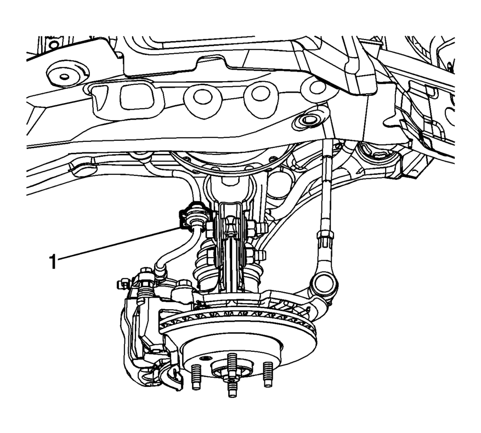
- Remove the front brake hose (1) from the front strut assembly.
- Remove the speed sensor wring harness from the front strut assembly, if needed.
- Remove the outer tie rod end from the steering knuckle. Refer to Steering Linkage Outer Tie Rod Replacement.
- Support the lower control arm with a jack stand.
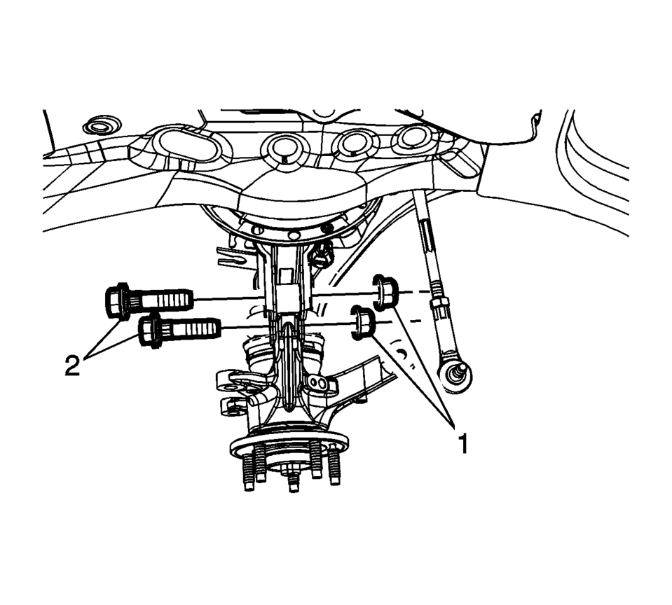
- Remove the front strut nut (1) and the bolt (2) from the front strut.
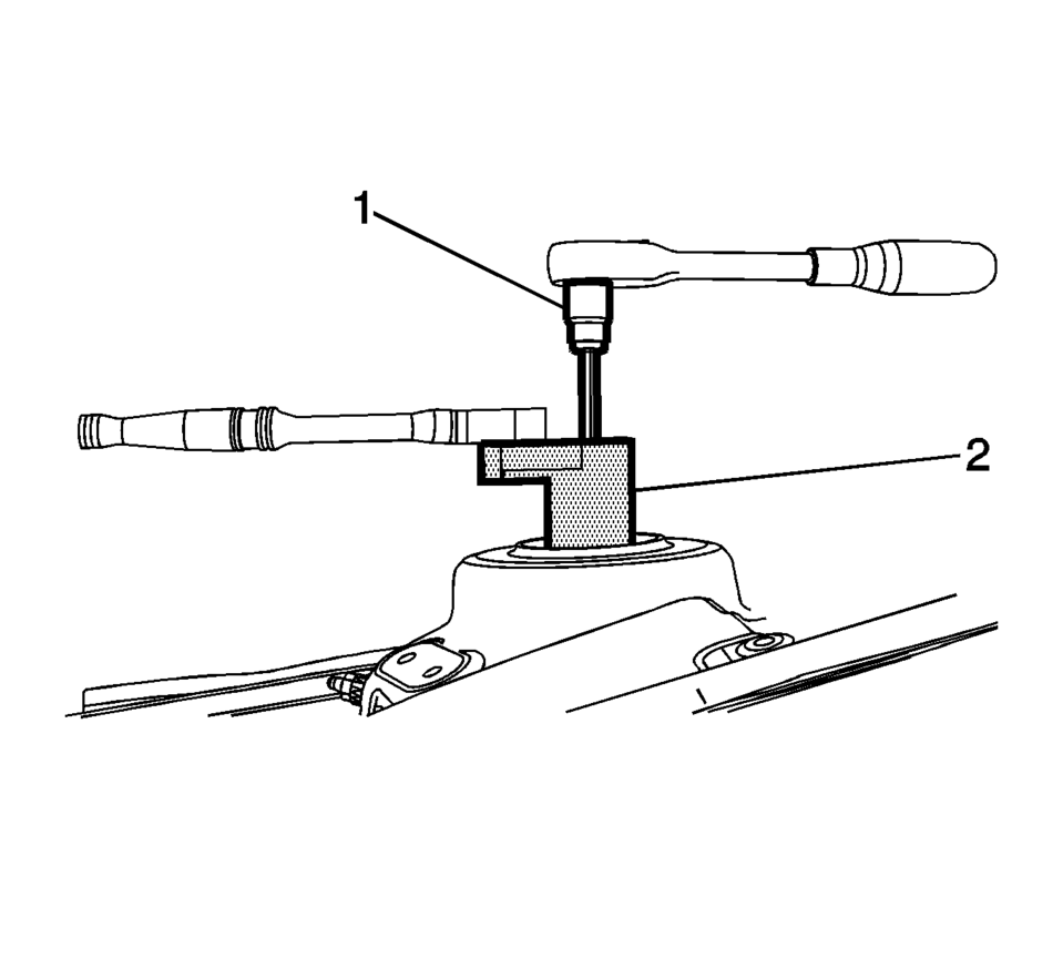
- Using the CH 49375 socket (2) and the proper size Torx® wrench, loosen the front strut nut.
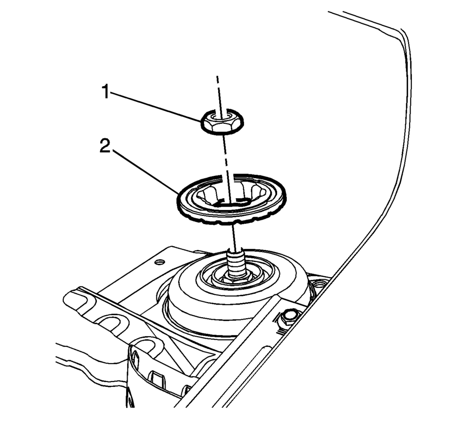
- Remove the front strut nut (1) and the retaining plate (2).
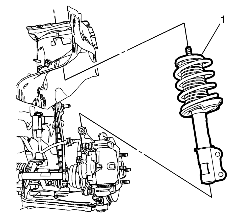
- Remove the front strut assembly from the vehicle (1).
- If removing the front strut assembly to service any of the front strut components, refer to Strut, Strut Component, or Spring Replacement.
- Installation Procedure
-
- Position the front strut assembly (1) in the vehicle.
- Install the front strut nut (1) and the retaining plate (2).
- Using the CH 49375 socket (2) and the proper size Torx® wrench
to hold the strut shaft, tighten the nut to 65 Y (48 lb ft)
.
- Install the front strut nut (1) and the bolt (2) from the front strut
and tighten the nut to 110 Y (82 lb ft)
.
- Install the stabilizer shaft link in the front strut assembly. Refer to Stabilizer Shaft Link Replacement.
- Remove the jack stand from the lower control arm.
- Install the outer tie rod end in the steering knuckle. Refer to Steering Linkage Outer Tie Rod Replacement.
- Install the speed sensor wiring harness on the front strut assembly, if needed.
- Install the front brake hose (1) on the front strut assembly.
- Install the tire and wheel assembly. Refer to Tire and Wheel Removal and Installation.
- Remove the support and lower the vehicle.
- Install the air inlet grille panel. Refer to Air Inlet Grille Panel Replacement.
Caution:
Refer to Fastener Caution.
 Liftgate Strut Replacement
Liftgate Strut Replacement
Callout
Component Name
1
Liftgate Strut
Warning: When a lift gate hold open device is ...
 Strut, Strut Component, or Spring Replacement
Disassembly Procedure
Remove the strut assembly from the vehicle. Refer to Strut Assembly
Removal and Installation.
Note: The spring is compressed when the strut move ...
Other materials:
Rear Wheelhouse Liner Replacement (Hatchback - Left)
Rear Wheelhouse Liner Replacement
Callout
Component Name
Preliminary Procedure
Remove the tire and wheel assembly. Refer to Tire and Wheel Removal and
Installation.
1
Rear Wheelhouse Panel Liner ...
SIR Inflator Module Handling and Storage Warning
Warning: When carrying an undeployed inflator module:
Do not carry the inflator module by the wires or connector.
Make sure the air bag opening points away from you.
When storing an undeployed inflator module:
Make sure the air bag opening points away from the surface o ...
Steering Linkage Inner Tie Rod Replacement
Steering Linkage Inner Tie Rod Replacement
Callout
Component Name
Preliminary Procedures
Raise and support the vehicle. Refer to Lifting and Jacking the
Vehicle.
Remove the steering gear boot. Refer to Steering Gear Boot ...

0.0116