Chevrolet Sonic Repair Manual: Timing Belt Inspection
Special Tools
- EN-6340 Locking Tool
- EN-6628-A Locking Tool
For equivalent regional tools, refer to Special Tools.
- Removal Procedure
-
- Remove the timing belt upper front cover. Refer to Timing Belt Upper Front Cover Removal.
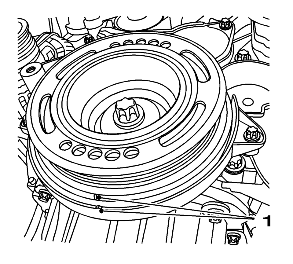
- Set the crankshaft balancer in the direction of the engine rotation to "1st cylinder TDC" (mark 1).
- Remove the camshaft cover. Refer to Camshaft Cover Removal.
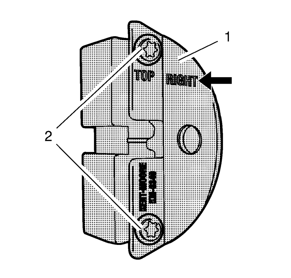
- Prepare the right half of the EN-6340 locking tool .
- Remove the 2 bolts (2).
- Remove the front panel (1) from the EN-6340 locking tool -right.
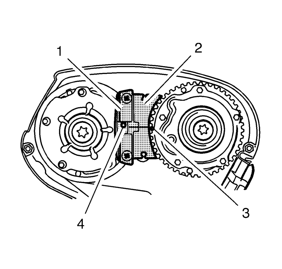
- The spot type marking (4) on the intake camshaft position actuator adjuster does not correspond to the groove of the EN-6340 locking tool - left (1) during this process, but must be somewhat above.
- The spot type marking (3) on the exhaust camshaft position actuator adjuster must correspond to the groove on EN-6340 locking tool - right (2).
- Insert the EN-6340 locking tool - left (1) and the EN-6340 locking tool - right (2) in the camshaft position actuator adjuster.
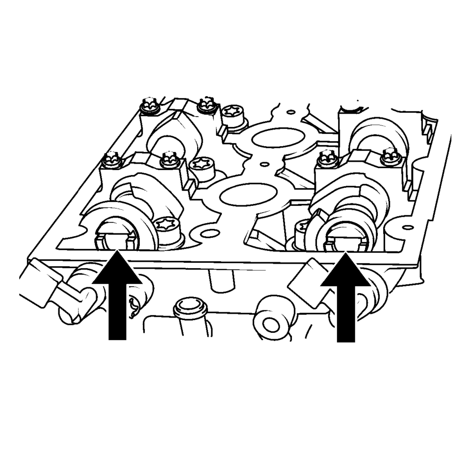
- Align the camshafts horizontally by the hexagon (arrows) until the EN-6628-A locking tool can be inserted in both camshafts.
- Insert the EN-6628-A locking tool (1) into the camshafts.


Note:
The right half of the EN-6340 locking tool can be recognized by the lettering “right?E arrow, on the tool.

Note:

Note:
If the EN-6628-A locking tool cannot be inserted, the timing must be set.

- Installation Procedure
-
- Remove the EN-6628-A locking tool .
- Remove the EN-6340 locking tool .
- Install the camshaft cover. Refer to Camshaft Cover Installation.
- Install the timing belt upper front cover. Refer to Timing Belt Upper Front Cover Installation.
 Timing Belt Center Front Cover Replacement
Timing Belt Center Front Cover Replacement
Callout
Component Name
Preliminary Procedure
Remove the timing belt upper front cover. R ...
 Timing Belt Installation
Special Tools
EN-6333 Locking Pin
EN-6340 Locking Tool
For equivalent regional tools, refer to Special Tools.
Note: The timing belt drive gear and oil pump housing must align.
...
Other materials:
Special Tools (MIT Tool Instructions)
Bluetooth Pairing for Vehicles with
Radio RPO: UF7
Either reset the pin code on the radio to 0000, or go under Device Info on
the radio and see what the pin code is (to enter it later on the MIT).
Turn the BT discoverable ON in the radio Bluetooth
settings.
Press Pair De ...
Windshield Washer Solvent Container Hose Replacement
Windshield Washer Solvent Container Hose Replacement
Callout
Component Name
Preliminary Procedure
Remove the left front wheelhouse liner. Refer to Front Wheelhouse Liner
Replacement.
1
Windshiel ...
Generator Pulley Replacement (LUV)
Generator Pulley Replacement
Callout
Component Name
Preliminary Procedure
Remove the generator. Refer to Generator Replacement.
1
Generator Pulley Nut Cap
2
Generator Pul ...
0.0089
