Chevrolet Sonic Repair Manual: Transmission Rear Mount Bracket Replacement
- Removal Procedure
-
- Raise and support the vehicle. Refer to Lifting and Jacking the Vehicle.
- Remove the front suspension skid plate, if equipped. Refer to Drivetrain and Front Suspension Frame Skid Plate Replacement.
- Using a suitable jack stand, support the rear of the powertrain.
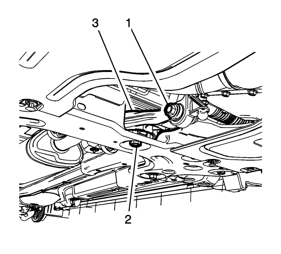
- Remove and DISCARD the transmission mount to bracket through bolt (1).
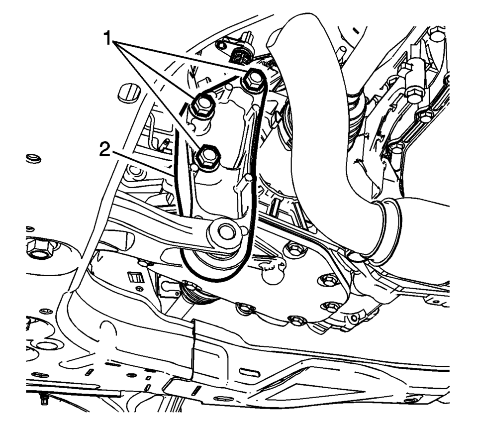
- Remove and DISCARD the transmission mount bracket bolts (1).
- Remove the transmission rear mount bracket (2).
- Installation Procedure
-
- Install the transmission rear mount bracket (2).
- Install the NEW transmission mount bracket bolts (1)
and tighten to 100 Y (74 lb ft) plus 30-45
degrees
.
- Install the NEW transmission mount to bracket through
bolt (1) and tighten nut to 80 Y (59 lb ft)
plus 45-60 degrees
.
- Remove the jack stand.
- Install the front suspension skid plate, if equipped. Refer to Drivetrain and Front Suspension Frame Skid Plate Replacement.
- Lower the vehicle.
Caution:
Refer to Fastener Caution.
 Transmission Indicators and Messages
The following transmission-related indicators and messages may be displayed on
the Instrument Panel Cluster (IPC). For a complete listing and description of all
vehicle indicators and messag ...
 Transmission Rear Mount Replacement
Removal Procedure
Raise and support the vehicle. Refer to
Lifting and Jacking the Vehicle.
Remove and DISCARD the rear transmission mount bracket
to rear mount thro ...
Other materials:
Front Floor Console Extension Replacement - Right Side
Front Floor Console Extension Replacement - Right Side
Callout
Component Name
1
Front Floor Console Extension
Procedure
Use a flat bladed plastic trim tool in order to release the retainers
securing the extens ...
Cylinder Head Assemble
Special Tools
EN-958 Valve Stem Seal Installer
EN-8062 Valve Spring Compressor
EN-8062-5 Adapter
EN-50717-2 Compressor Assembly of EN-50717 Kit
For equivalent regional tools, refer to Special Tools.
Lubricate the valve stem and the valve guide with clean engine oil.
...
Control Solenoid Valve and Transmission Control Module Assembly Replacement
Removal Procedure
Remove the transmission control valve body cover.
Refer to Control Valve Body Cover Replacement.
Disconnect the output speed sensor electrical connector (2).
Disconnect the shift position switch electrical connector (3).
Disconn ...

0.0062