Chevrolet Sonic Repair Manual: Valve Stem Oil Seal and Valve Spring Replacement
Special Tools
- 207649 Rod Hairpin Clips
- 547324 Flange Screws
- EN-840 Pliers / Remover
- EN-958 Installer
- EN-45059 Angle Meter
- EN-50717 Kit
- J-43649–2 Rods
For equivalent regional tools, refer to Special Tools.
- Removal Procedure
-
- Remove the spark plugs. Refer to Spark Plug Replacement.
- Remove the camshaft position actuator. Refer to Camshaft Sprocket Replacement.
- Remove both camshafts. Refer to Camshaft Replacement.
- Remove the valve lifter. Refer to Valve Lifter Replacement.
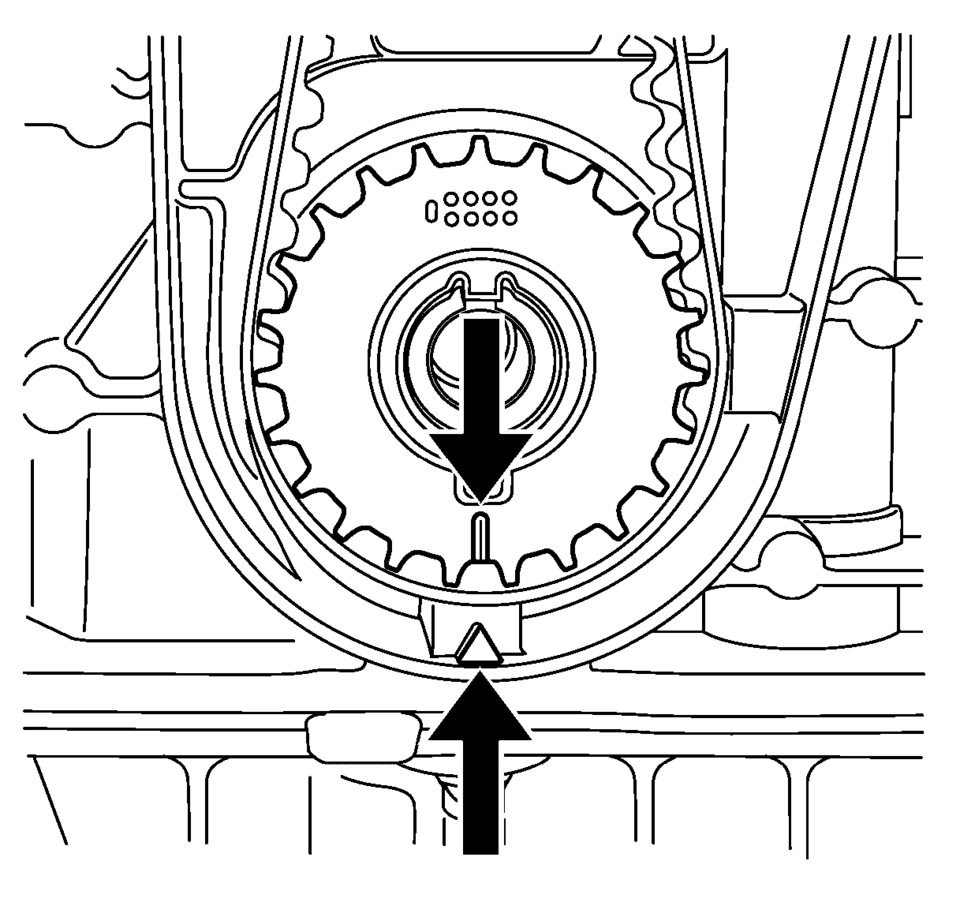
- For cylinder 1 and 4 set the crankshaft to TDC marking, cylinder number 1. Use the crankshaft balancer bolt.
- For cylinder 2 and 3, set the crankshaft BDC (180 degrees from TDC marking). Use the crankshaft balancer bolt.
- Shift to 1. gear (MT) or park position (AT) and apply the park brake.
Note:
Wheels must contact the ground.
- Valve Stem Oil Seal Removal
-
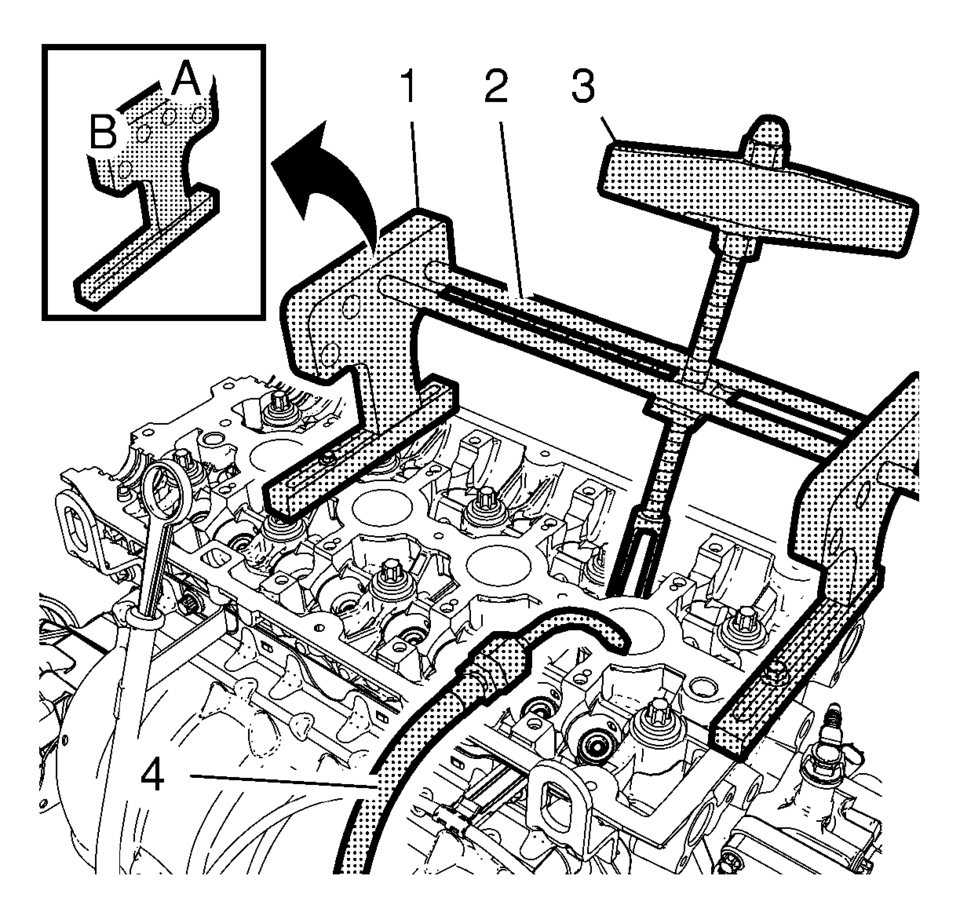
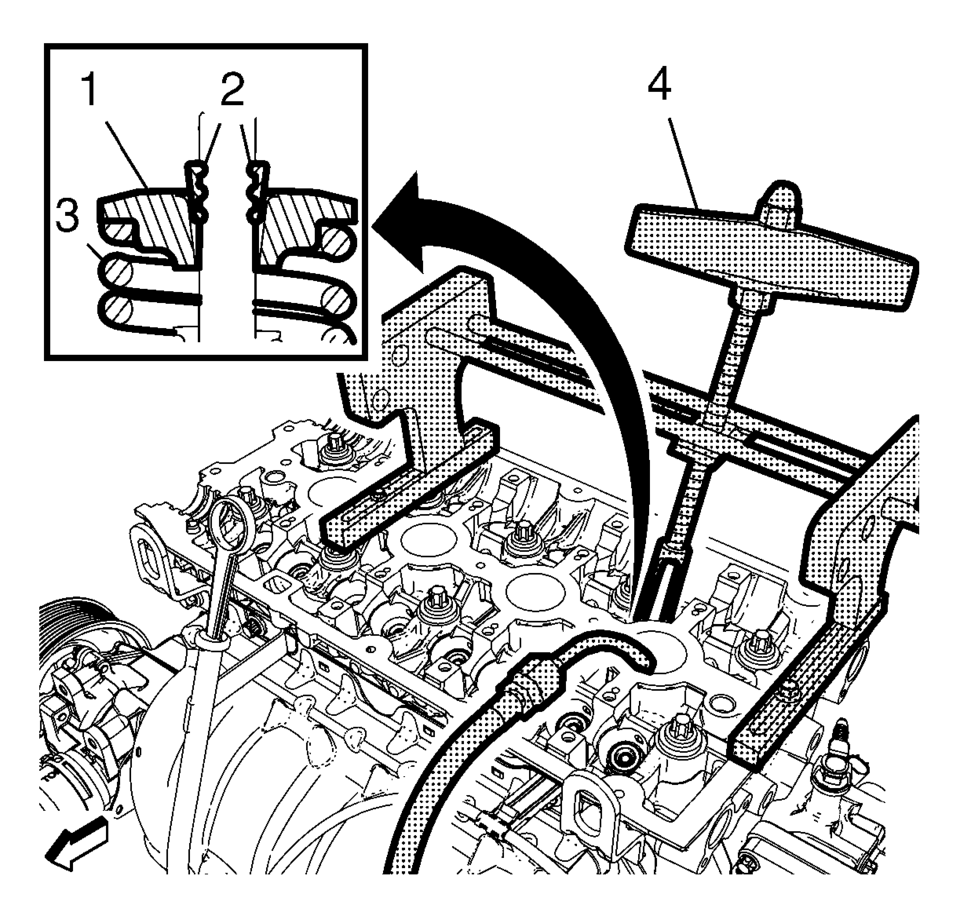
- Install the 2 EN-50717–1 stands (1) to the cylinder head and fix them with the 547324 screws.
- Install the 2 J-43649-2 rods (2) and the EN-51717–2 compressor (3) to the B-side of the EN-50717–1 stands. Secure the rods with the 207649 clips then.
- Install an suitable air pressure adapter (4) to the spark plug hole.
- Apply air pressure to the corresponding cylinder.
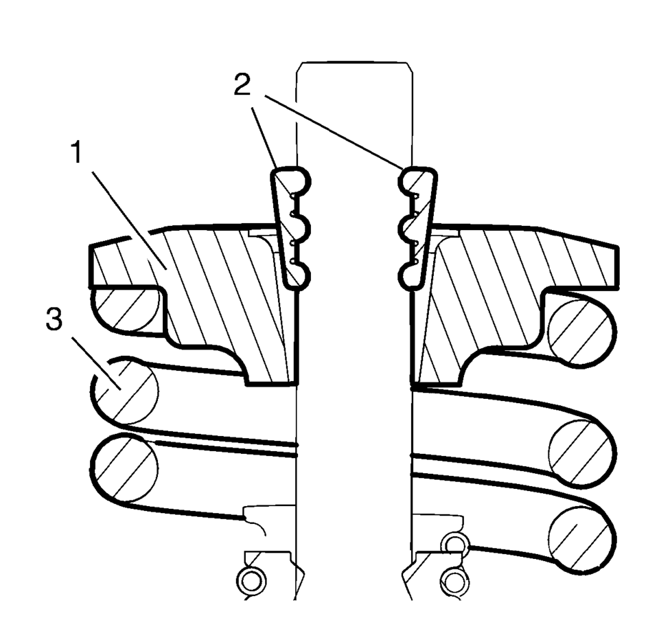
- Position the EN-51717–2 compressor (3) so that its adapter proper contacts the valve spring retainer and pretension the compressor.
- Apply pressure to the EN-50717–2 compressor to push down the vale spring retainer (1) and compress the valve spring (3) until the valve keys (2) are free from tension. Carefully remove the valve keys then.
- Release the tension from the EN-50717–2 compressor.
- Remove the valve spring retainer (1) and the valve spring (3).
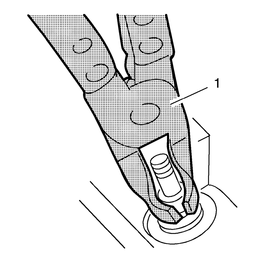
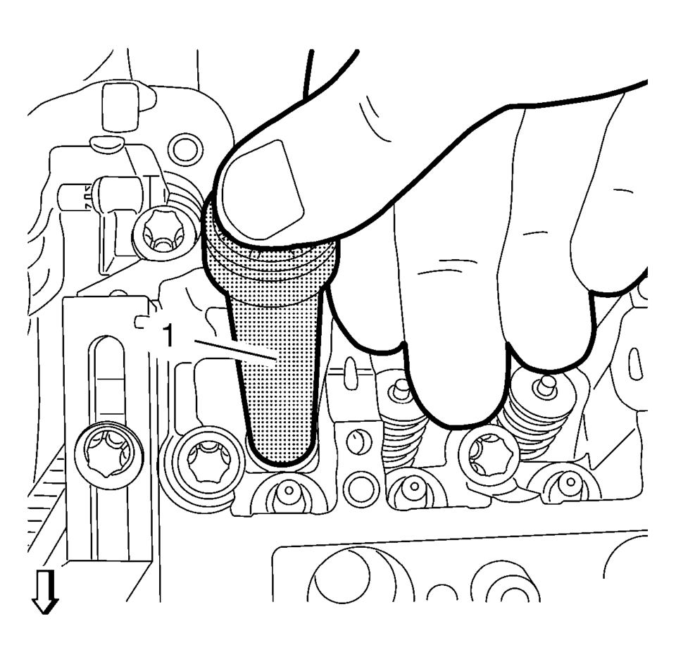
- Remove and DISCARD the valve stem oil seal, using the EN-840 pliers (1).
Warning:
Valve springs can be tightly compressed. Use care when removing the retainers and plugs. Personal injury could result.
- Valve Stem Oil Seal Installation
-
- Install the NEW valve stem oil seal, using the EN-958 installer (1).
- Loosely install the valve spring and the valve spring retainer.
- Using the EN-51717–2 compressor (4), push down the valve spring retainer (1) and compress the valve spring (3) until the valve keys (2) can be inserted. Carefully insert the valve keys then, so that they are proper installed to the valve stem grooves.
- Carefully release the tension from the EN-50717–2 compressor.
- Inspect the valve keys and valve spring retainer for proper seat.
- Repeat the procedure with the remaining valves and cylinders. Transfer the EN-50717–1 stands and the EN-51717–2 compressor as needed.
- Take care that air pressure is always applied to the combustion chamber of the treated cylinder.
Note:
Lubricate the NEW valve stem oil seal with clean engine oil.
Caution:
The valve stem keys must correctly seat in the valve spring cap. Engine damage may occur by not installing properly.
- Installation Procedure
-
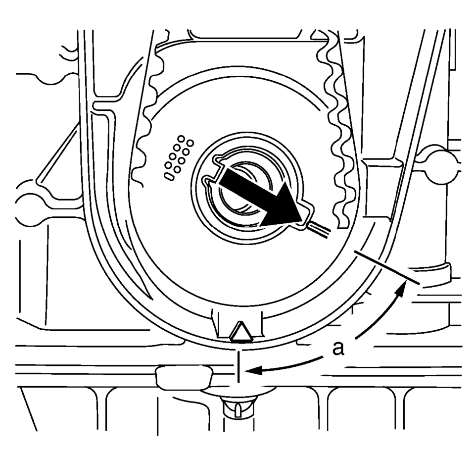
- Set the crankshaft in direction of engine rotation to 60 degrees
(a) before TDC. Use the EN-45059 meter and the crankshaft balancer bolt.
- Install the valve lifter. Refer to Valve Lifter Replacement.
- Install both camshafts. Refer to Camshaft Replacement.
- Install the camshaft position actuator. Refer to Camshaft Sprocket Replacement.
- Install the spark plugs. Refer to Spark Plug Replacement.
- Set the crankshaft in direction of engine rotation to 60 degrees
 Tread Wear Indicators Description
The original equipment tires have tread wear indicators that show when you should
replace the tires.
The location of these indicators are at 60 degree intervals around the outer
diamet ...
 Wheel Replacement
Replace any wheel that is bent, cracked, or badly rusted or corroded. If wheel
nuts keep coming loose, the wheel, wheel bolts, and wheel nuts should be replaced.
If the wheel leaks air, replace it ...
Other materials:
Child Restraint Systems
Rear-Facing Infant Seat
A rear-facing infant seat provides restraint with the seating surface against
the back of the infant.
The harness system holds the infant in place and, in a crash, acts to keep the
infant positioned in the restraint.
Forward-Facing Child Seat
A forward-facing chil ...
Retained Accessory Power Description and Operation
Retained Accessory Power
RAP Description and Operation Block Diagram
K9Body
Control
ModuleK73Telematics
Communication
Interface
Control ModuleA11RadioKR76Retained
Accessory
Power
Relay
Hard-W ...
Rear Window Wiper Motor Grommet Replacement
Rear Window Wiper Motor Grommet Replacement
Callout
Component Name
Preliminary Procedure
Remove the rear window wiper motor. Refer to Rear Window Wiper Motor
Replacement.
1
Rear Window Wiper Mot ...

0.0057