Chevrolet Sonic Repair Manual: Wheel Drive Shaft Outer Joint Inspection
- Disassembly Procedure
-
- Remove the outer constant velocity (CV) joint and boot from the wheel drive shaft. Refer to Front Wheel Drive Shaft Outer Joint and Boot Replacement.
- Remove any lubricant from the CV joint.
- Install the outer CV joint assembly in a soft jawed vise.
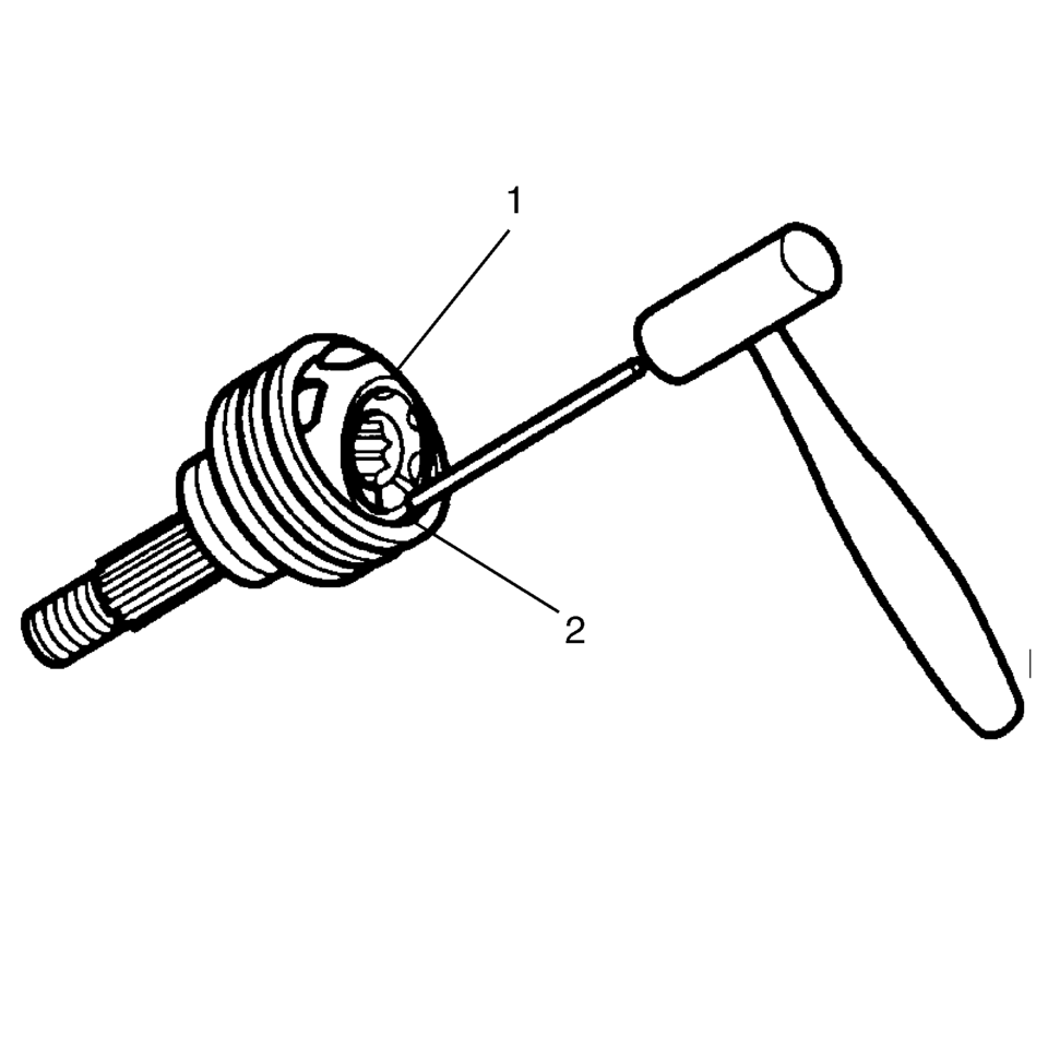
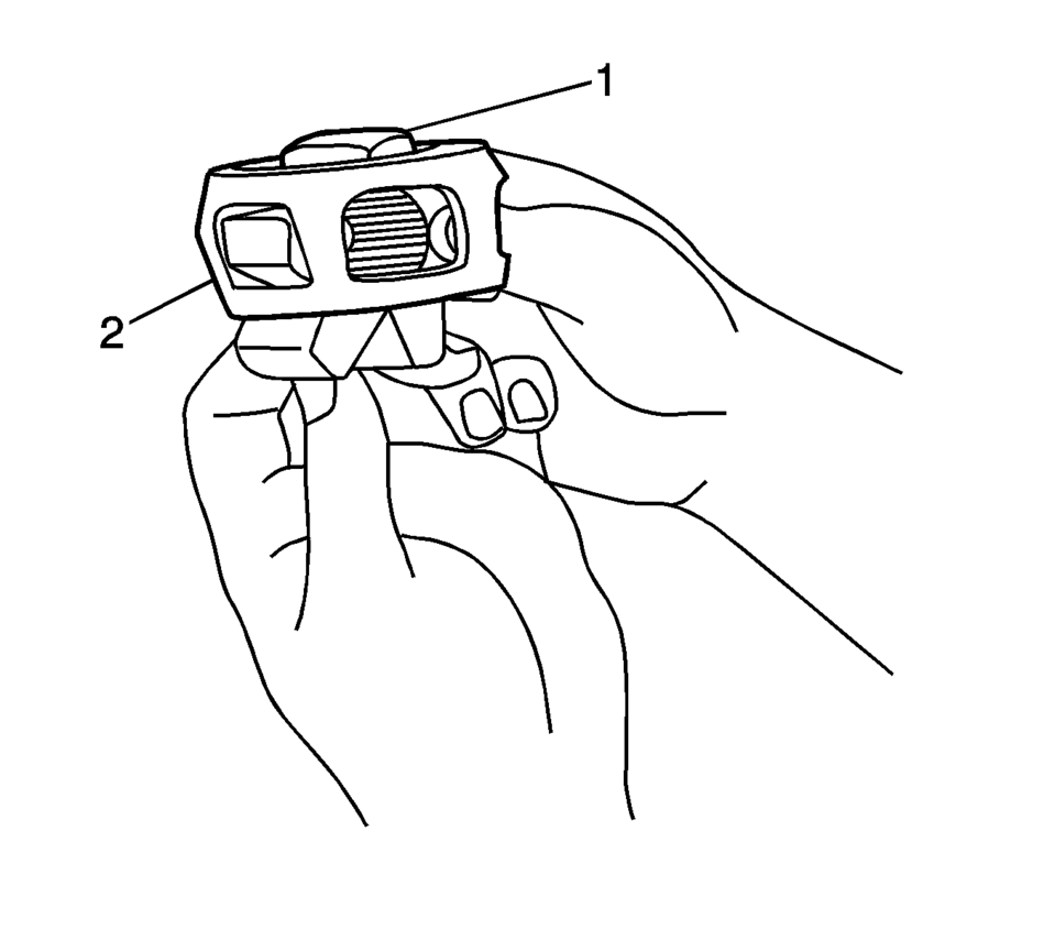
- Using a brass drift (1), gentle tap the cage (2) until the ball bearing can be removed from the cage (2).
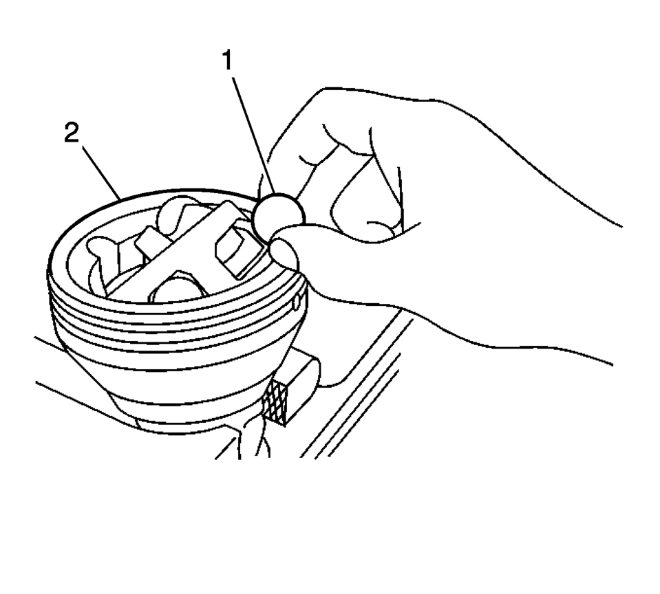
- Using a small screwdriver, remove the ball bearings (1) from the CV joint (2).
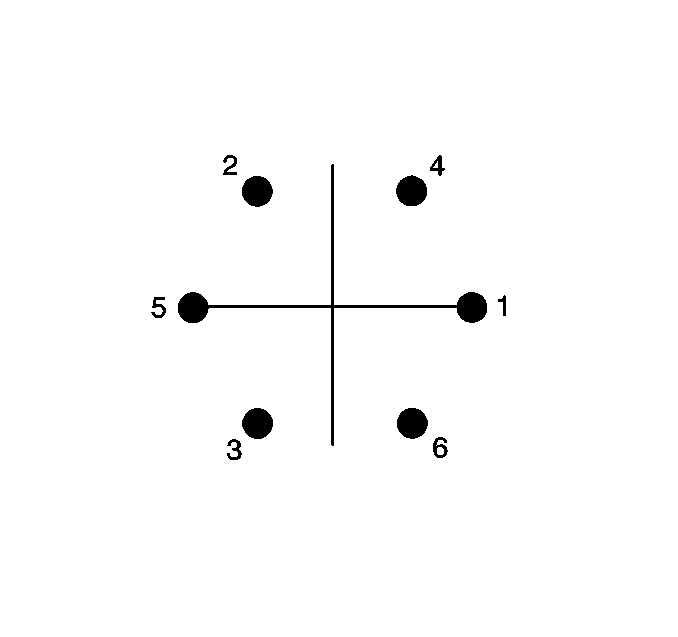
- Remove the ball bearings from the CV joint in sequence.
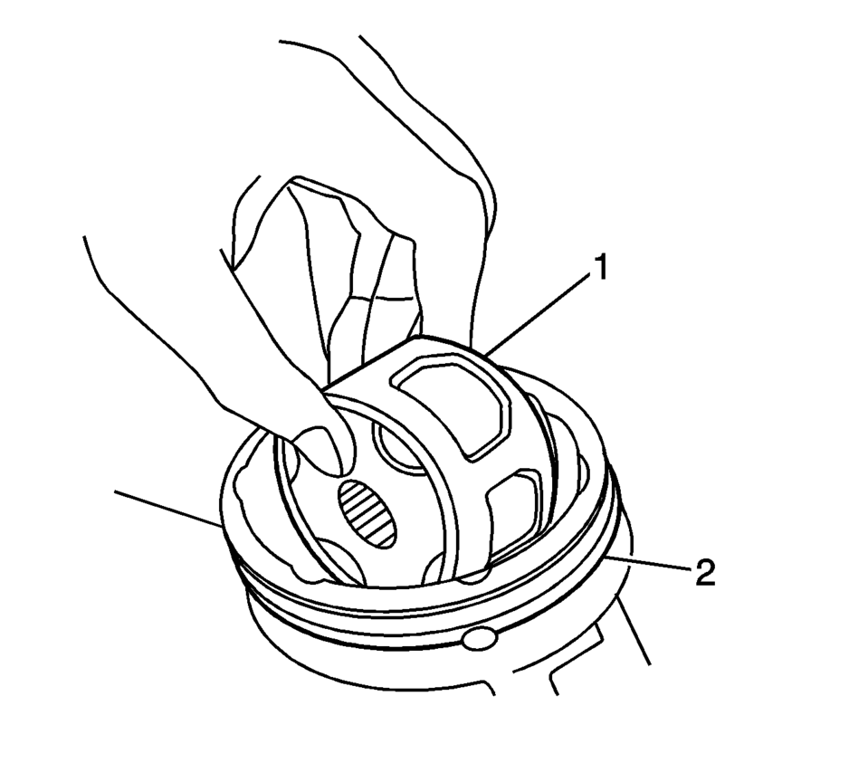
- Position the cage (1) at a 90 degrees to the centerline of the outer race (2).
- Align the cage windows with the lands of the outer race (2).
- Lift and remove the cage (1) and the inner race from the outer race (2).
- Position the cage (2) and the inner race (1) so that the larger radius corners of the cage windows are up.
- Rotate the inner race (1) 90 degrees to the center line of the cage (2).
- Align the lands of the inner race (1) with the windows of the cage (2).
- Move the inner race (1) land into the cage window (2).
- Rotate the inner race (1) down and remove it from the cage (2).
- Clean the following items thoroughly with the proper cleaning solvent:
Note:
Position the cage and the inner race so they are level.
Note:
The following procedure will have to be repeated until all the ball bearing are removed from the cage.
Note:
Position the cage so that the larger radius corners of the cage windows are facing up.
- The inner race
- The outer race
- The cage
- The ball bearings
- The exposed end of the wheel drive shaft
Note:
The internal parts of the CV joint are NOT SERVICED separately. The outer CV joint is serviced as an assembly.
- If any of the above items are found to have excessive wear or are damaged, replace the outer CV joint as an assembly.
- Assembly Procedure
-
- Position the cage (2) so that the larger radius corners of the cage windows are up.
- Position the inner race (1) 90 degrees to the centerline of the cage (2).
- Insert the inner race (1) through the bottom of the cage (2).
- Align the lands of the inner race (1) with the windows of the cage (2).
- Move the inner race (1) land into the cage window (2).
- Rotate the inner race (1) down and remove it from the cage (2).
- Rotate the inner race (1) within the cage (2) so that the grooved surface of the inner race (1) is facing up.
- Align the inner race (1) ball bearing tracks with the cage (2) windows.
- Wrap a clean shop towel around the CV joint outer race spined shaft.
- Place the outer race (2) vertically in a bench vise.
- Position the cage (1) and the inner race at a 90 degrees to the centerline of the outer race (2).
- With the inner race and the cage (1) assembly in a vertical position, insert the cage and the inner race into the outer race (2).
- Position the cage (2) and the inner race so that they are level in the vise.
- Rotate the appropriate component(s), and align the cage windows and the inner race ball bearing (1) tracks with the outer race ball bearing tracks.
- Position a cage window and the inner race ball bearing track for the ball bearing installation.
- Press down on the cage following one of the outer race ball bearing (1) tracks.
- Install the ball bearing through the cage window onto the inner race ball bearing (1) track.
- After the first ball bearing (1) has been installed, use a brass drift and a hammer and gently tap the cage in order to drive the cage and the inner race down completely in the outer race.
- Position the cage and the inner race so that they are level.
- Using a plastic hammer, lightly tap the ball bearing (1) into place.
- Install the ball bearings in sequence.
- Repeat steps 18 thru 20 until all the ball bearings are installed.
- Install the outer CV joint and boot on the wheel drive shaft. Refer to Front Wheel Drive Shaft Outer Joint and Boot Replacement.
Note:
The larger radius corners of the cage windows should be positioned up and the grooved surface of the inner race should be visible.
Note:
When performing the following procedure, the opposing cage (2) window and the inner ball bearing (1) track will be accessible for the ball bearing installation.
Note:
The following service procedure will have to be performed after each ball bearing (1) has been installed.
Note:
After the ball bearing (1) has been installed, there should be NO GAP between the ball bearing and the inner race.
 Wheel Drive Shaft Inner Joint Inspection
Inspection Procedure
Remove the front wheel drive shaft inner joint and boot. Refer to Front
Wheel Drive Shaft Replacement.
Remove the wheel drive shaft tripod bushing ...
 Wheel Drive Shafts Description and Operation
Front wheel drive axles are flexible assemblies.
Front wheel drive axles consist of the following components:
A front wheel drive shaft tripot joint (inner joint)
A front wheel drive shaft con ...
Other materials:
Wheel Replacement
Replace any wheel that is bent, cracked, or badly rusted or corroded. If wheel
nuts keep coming loose, the wheel, wheel bolts, and wheel nuts should be replaced.
If the wheel leaks air, replace it. Some aluminum wheels can be repaired. See your
dealer if any of these conditions exist.
Your de ...
Radio and Telephone Control Switch Replacement
Radio and Telephone Control Switch Replacement
Callout
Component Name
Preliminary Procedure
Remove the sterring wheel inflatable restraint module. Refer to
Airbag Steering Wheel Module Replacement.
1
...
Hood Hold-Open Rod Replacement
Hood Hold-Open Rod Replacement
Callout
Component Name
1
Hood Hold-Open Rod
Warning: When a hood hold open device is being removed or
installed, provide alternate support to avoid the possibility of damage
...

0.0071