Chevrolet Sonic Repair Manual: Air Cleaner Element Replacement
- Removal Procedure
-
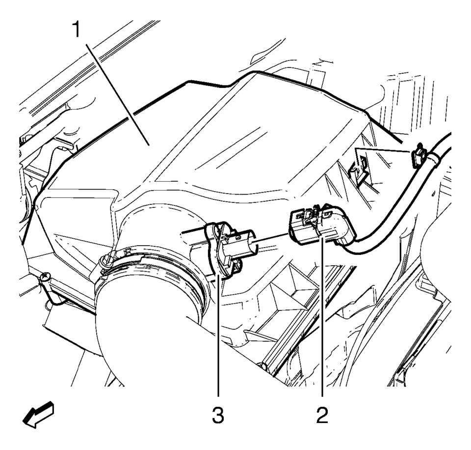
- Disconnect mass air flow sensor wiring harness plug (2) from mass air flow sensor (3).
- Unclip mass air flow sensor wiring harness retainer clip from air cleaner housing (1).
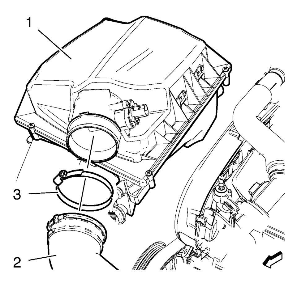
- Remove the air cleaner outlet duct clamp (3).
- Remove the air cleaner outlet duct (2) from air cleaner housing (1).
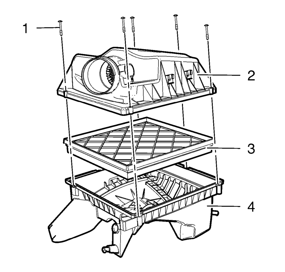
- Remove the 5 air cleaner housing bolts (1).
- Remove the air cleaner upper housing (2) from the air cleaner lower housing (4).
- Remove the air cleaner element (3).
- Installation Procedure
-
- Install the air cleaner element (3).
- Install the air cleaner upper housing (2) to the air cleaner lower housing (4).
- Install the 5 air cleaner housing bolts (1).
- Install the air cleaner outlet duct (2) to the air cleaner housing (1).
- Install the air cleaner outlet duct clamp (3).
- Clip in mass air flow sensor wiring harness retainer clip to air cleaner housing (1).
- Connect the mass air flow sensor wiring harness plug 2) to the mass air flow sensor (3).
Caution:
Refer to Fastener Caution.
 Air Cleaner Assembly Replacement
Air Cleaner Assembly Replacement
Callout
Component Name
1
Air Cleaner Outlet Duct Clamp.
Procedure
Loosen clamp a ...
 Air Cleaner Inlet Duct Replacement
Removal Procedure
Remove the right front wheelhouse liner. Refer to Front Wheelhouse Liner
Replacement.
Remove the upper intake air duct plastic fastener (1).
...
Other materials:
Battery Description and Operation
Warning: Batteries produce explosive gases, contain corrosive acid,
and supply levels of electrical current high enough to cause burns. Therefore,
to reduce the risk of personal injury when working near a battery:
Always shield your eyes and avoid leaning over the battery whenever
...
Engine Coolant Thermostat Replacement (LUV)
Removal Procedure
Drain the cooling system. Refer to Cooling System Draining and Filling.
Remove the air cleaner outlet duct. Refer to Air Cleaner Outlet Duct
Replacement.
Remove the engine coolant temperature sensor connector (1).
Disconnect the radi ...
Engine Oil Cooler Replacement
Removal Procedure
Disconnect battery negative cable. Refer to Battery Negative Cable Disconnection
and Connection.
Drain engine coolant. Refer to Cooling System Draining and Filling
Remove the turbocharger oil feed pipe. Refer to Turbocharger Oil Feed
Pipe Replacement ...

0.0062