Chevrolet Sonic Repair Manual: Crankshaft and Bearing Cleaning and Inspection
Special Tools
- EN-45059 Torque Angle Sensor Kit
- GE-571-B Dial Gauge
For equivalent regional tools, refer to Special Tools.
- Crankshaft End Play, Check
-
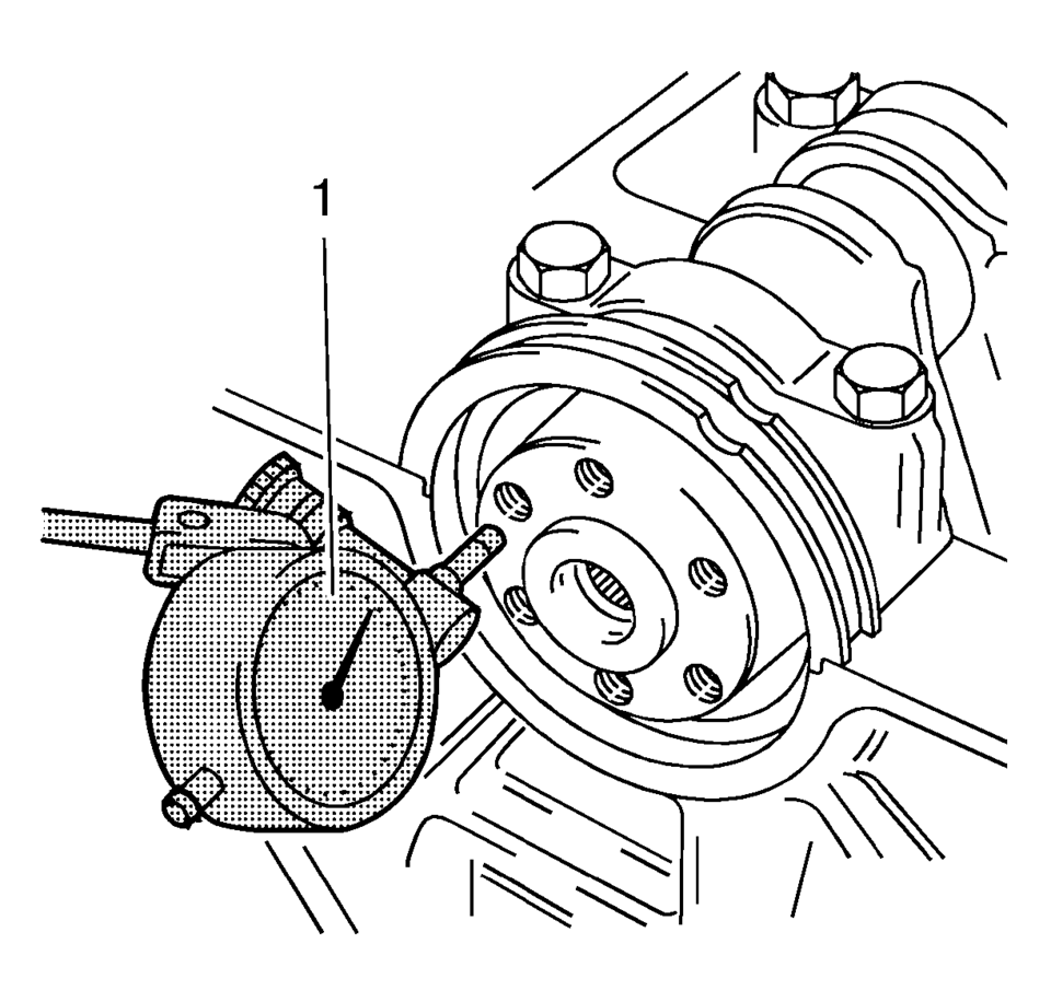
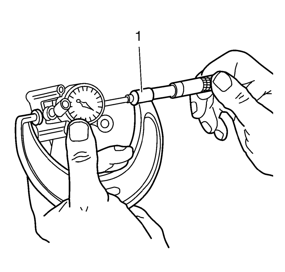
- Install the GE-571-B gauge (1).
- Install in the holder on the front of the engine block.
- Place the dial gauge plunger against the crankshaft and adjust.
- Measure the longitudinal play of the crankshaft.
- Move the crankshaft in the longitudinal direction.
- Permissible crankshaft end play: 0.100?E.202 mm (0.0039?E.0080 in)
- Remove the GE-571-B gauge .
Note:
Crankshaft attached with crankshaft bearing caps.
- Crankshaft Out-of-Round, Check
-
- Insert the crankshaft in the engine block.
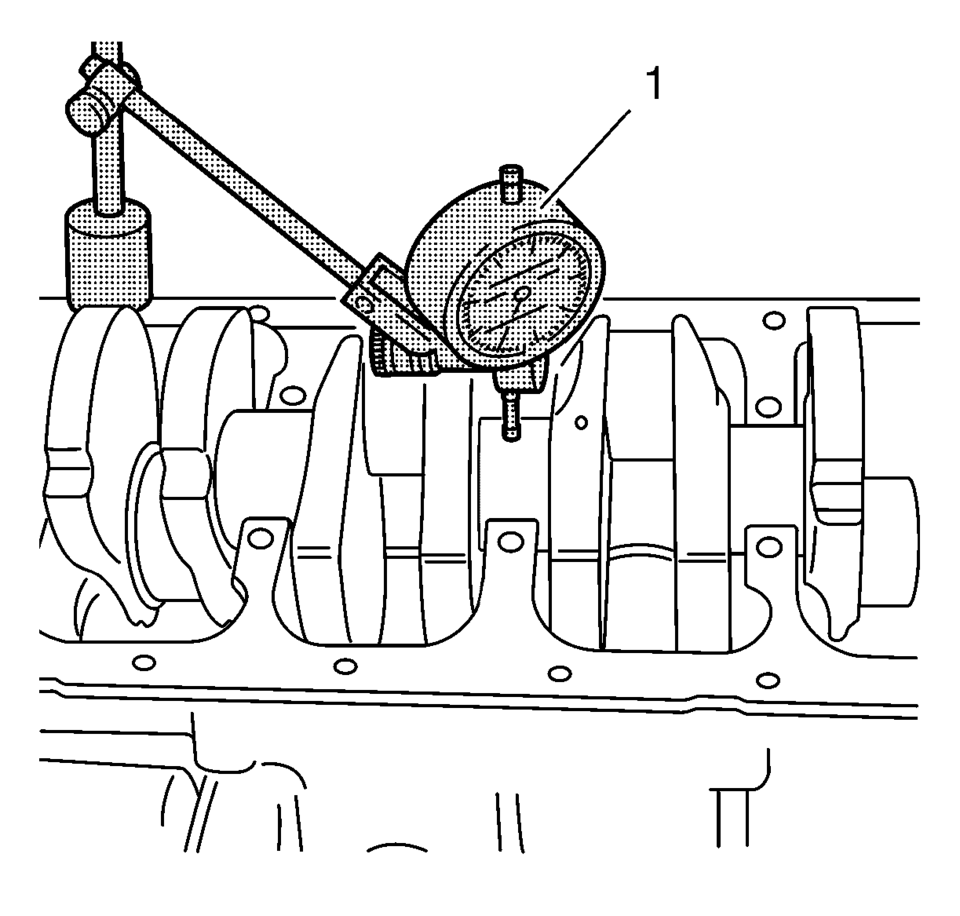
- Install the GE-571-B gauge .
- Attach to the bracket on the engine block.
- Place the dial gauge plunger against the crankshaft bearing journal and adjust.
- Check the rotational play of the crankshaft.
- Turn the crankshaft evenly.
- Maximum permissible rotational play: 0.03 mm (0.001 in).
- Remove the GE-571-B gauge (1).
Note:
Crankshaft removed.
- Check Crankshaft Bearing Clearance (With Plastigage)
-
- Crankshaft removed.
- Do not rotate the crankshaft.
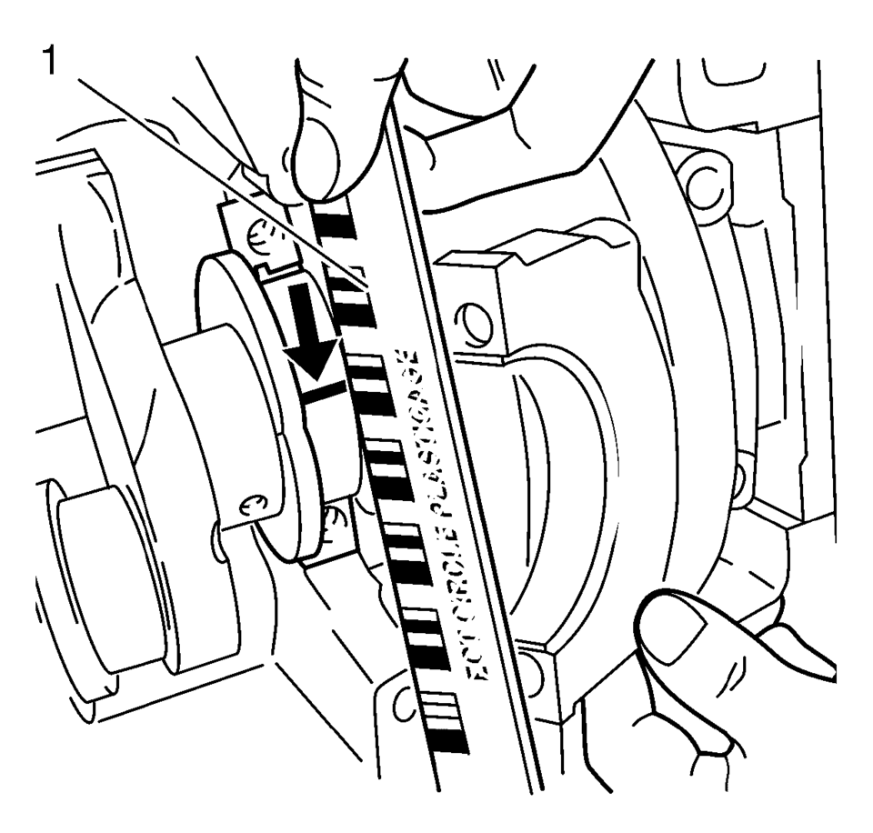
- Lay on plastigage.
Lay out plastigage (flexible plastic thread) around the entire width of the con-rod bearing journal (1).
- Note the correct tightening sequence.
- The bolts can be reused for checking the crankshaft bearing play.
- Install the crankshaft bearing cap. Tighten the 2 crankshaft bearing cap bolts in 3 passes. Use the EN-45059 sensor kit :
- First pass to 50 Y (37 lb ft)
- Second pass to 45°
- Third pass to 15°
- Remove the 2 crankshaft bearing cap bolts.
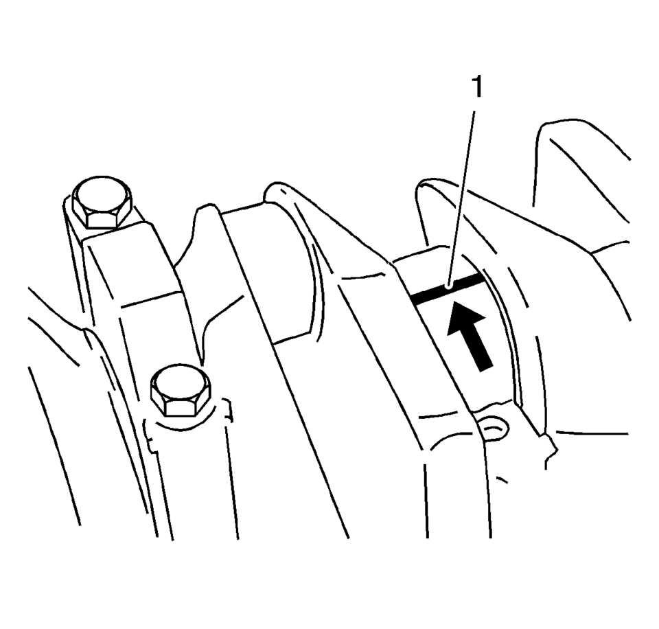
- Measure the crankshaft bearing play.
- Compare the width of the flattened plastic thread (arrow) to the measuring scale.
- Permissible crankshaft bearing play: 0.005?E.059 mm (0.0002?E.0023 in).
Note:
Caution:
Refer to Fastener Caution.
Note:
Note:
When reading the value, do not confuse millimeters and inches on the measuring scale (1).
- Check Crankshaft Bearing Clearance (With Micrometer Gauge Internal Measuring Device)
-
- Note the correct tightening sequence.
- The bolts can be reused for checking the crankshaft bearing play.
- Install the crankshaft bearing cap with the crankshaft bearing clips
to the cylinder block.
Tighten the 2 crankshaft bearing cap bolts in 3 passes. Use the EN-45059 sensor kit :
- First pass to 50 Y (37 lb ft)
- Second pass to 45°
- Third pass to 15°
- Install the inner plunger and calibrate with the micrometer gauge (1).
- Measure the crankshaft bearing diameter at 3 points.
Note:
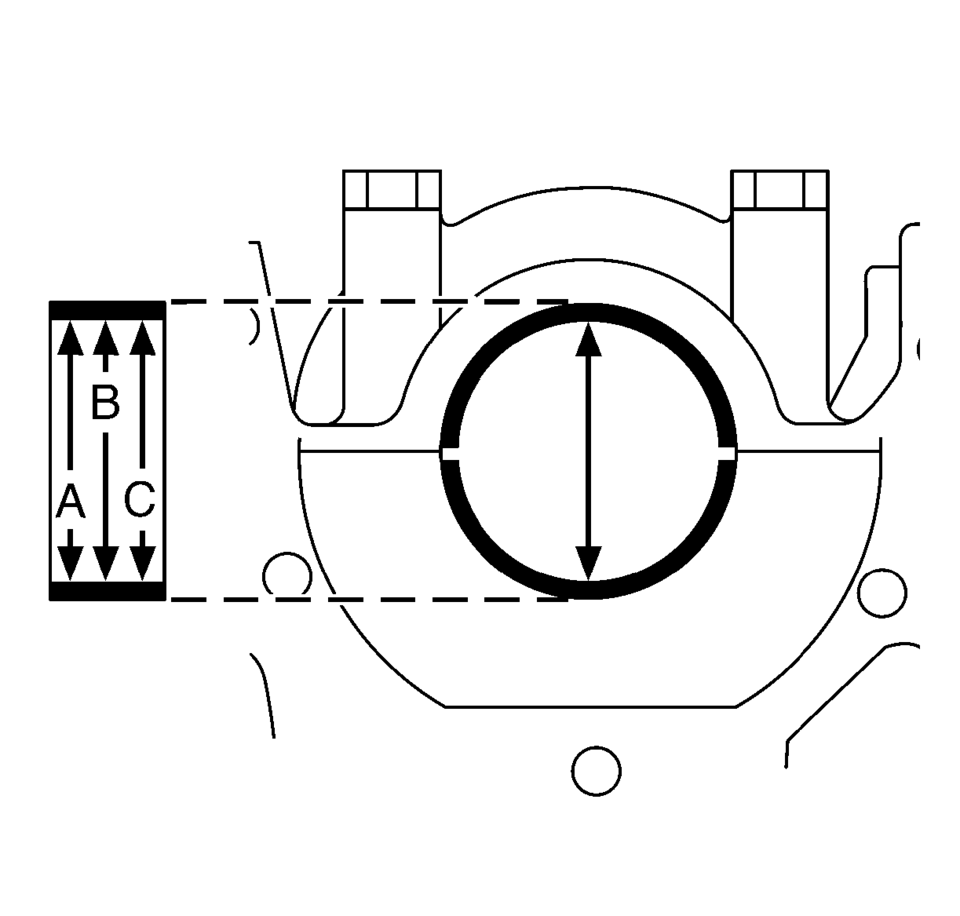
- Measure at points A, B and C with the internal measuring device.
- Calculate the average crankshaft bearing diameter.
- Formula: A + B + C /3.
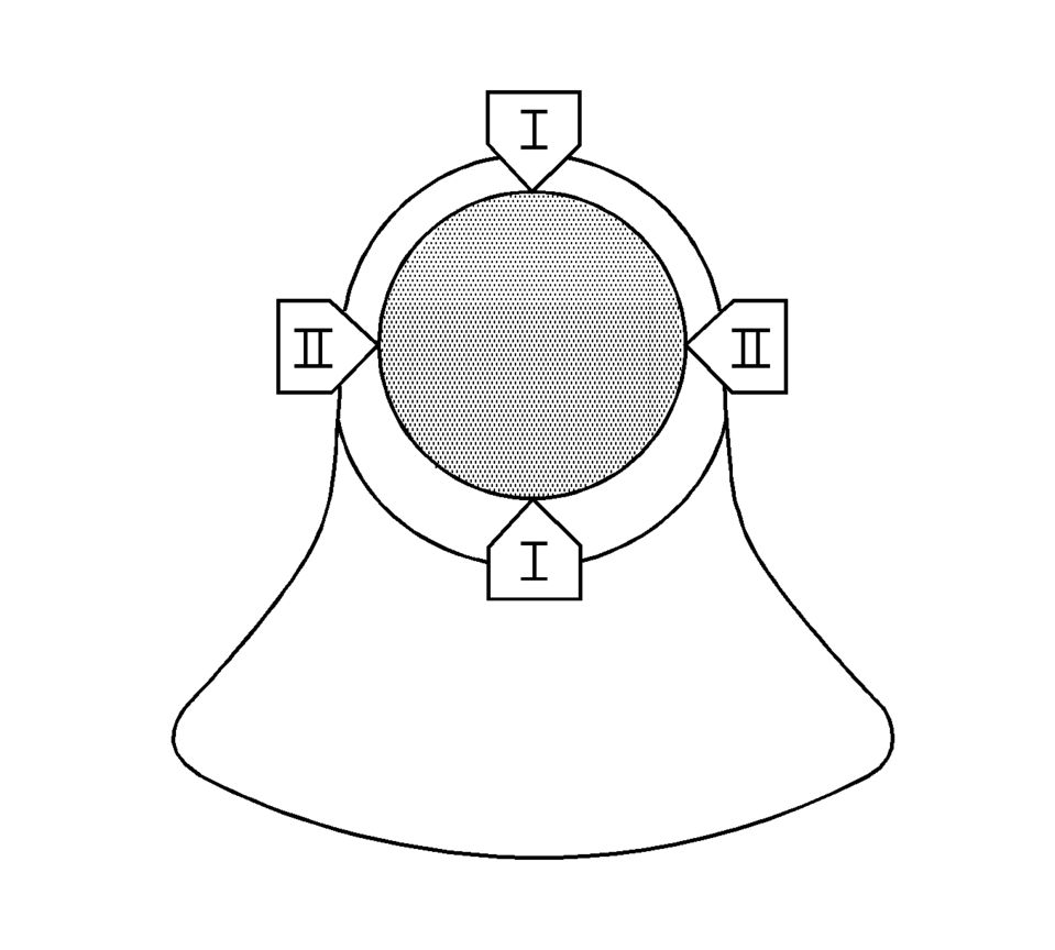
- Measure the crankshaft bearing journal diameter at 2 points.
Measure at points I and II with the micrometer gauge.
- Calculate the average crankshaft bearing journal diameter.
Formula: I + II/2.
- Determine the crankshaft bearing play.
Calculation formula: average crankshaft bearing diameter minus average crankshaft bearing journal diameter.
- Nominal-Actual comparison.
Permissible crankshaft bearing play: 0.005?E.059 mm (0.0002?E.0023 in).
 Crankshaft Position System Variation Learn
Note: The crankshaft position sensor system variation learn procedure
is required when the following service procedures have been performed, regardless
of whether DTC P0315 is set:
...
 Crankshaft and Bearing Installation
Special Tools
EN-45059 Torque Angle Sensor Kit
For equivalent regional tools, refer to Special Tools
Note: Inspect the installation position.
Install the crankshaft bearing cl ...
Other materials:
Airbag Steering Wheel Module Coil Centering
Note: If a double wire harness strap is installed onto the wire
harness assembly and steering column, the original holder for the wire strap(s)
MUST be reused during installation.
Remove the wire harness strap(s) where necessary.
Caution: The new SIR coil assembly will ...
Heated Oxygen and Oxygen Sensor Caution
Caution: Do not remove the pigtail from either the heated oxygen sensor
(HO2S) or the oxygen sensor (O2S). Removing the pigtail or the connector will
affect sensor operation.
Handle the oxygen sensor carefully. Do not drop the HO2S. Keep the in-line
electrical connector and the louver ...
Drive Range, First Gear (Gen 2)
As the vehicle speed increases, the transmission control module (TCM) receives
input signals from the automatic transmission input and output speed sensors, throttle
position sensor and other vehicle sensors to determine the precise moment to de-energize
or ?urn OFF?the shift solenoid, and to ...

0.0073