Chevrolet Sonic Repair Manual: Fuel Pump Flow Control Module Replacement
|
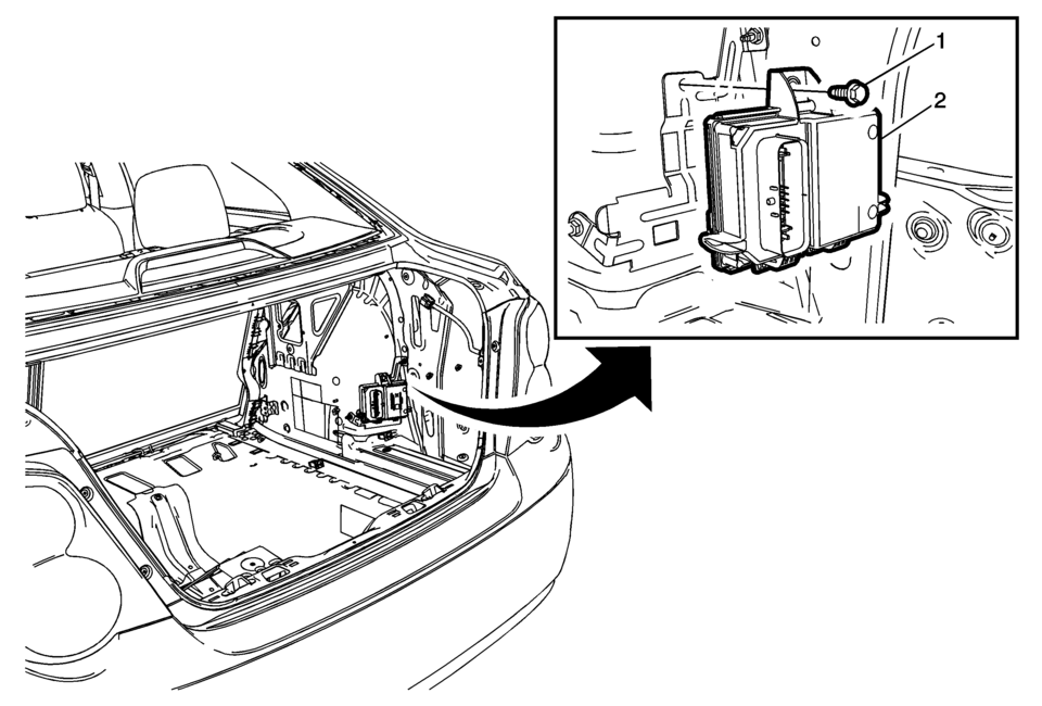
Callout |
Component Name |
|---|---|
Preliminary Procedures
|
|
|
1 |
Fuel Pump Control Module Fastener Caution: Refer to Fastener Caution.
10 Y (89 lb in) |
|
2 |
Fuel Pump Control Module Caution:
|
 Fuel Pressure Relief
Special Tools
EN-34730-91 Pressure Tester
For equivalent regional tools, refer to Special Tools.
Warning: Gasoline or gasoline vapors are highly flammable. A fire
could occur if an ig ...
 Fuel System Cleaning
Note: If the fuel filter is plugged, the fuel tank should be inspected
internally and cleaned if necessary.
Drain the fuel tank. Refer to
Fuel Tank Draining.
Remove the f ...
Other materials:
Rear Window Wiper Motor Replacement (Hatchback)
Rear Window Wiper Motor Replacement
Callout
Component Name
Preliminary Procedure
Open and support the liftgate assembly.
Remove the rear window wiper arm assembly. Refer to Rear Window
Wiper Arm Replacement.
Remove th ...
Engine Flywheel Removal
Special Tools
EN-652 Flywheel Holder
For equivalent regional tools, refer to Special Tools.
Install EN-652 holder (1) to hold the engine flywheel (2).
Remove and DISCARD the 6 engine flywheel bolts (2).
Remove the engine flywheel (1).
...
Cockpit
Example
The cockpit of the Nissan Armada is engineered to provide maximum control, comfort,
and advanced driver assistance integration. Every switch and control element is
strategically positioned to ensure intuitive access, allowing the driver of the
Nissan Armada to stay focused on the ...

0.0058