Chevrolet Sonic Repair Manual: Instrument Panel Upper Trim Panel Replacement - Right Side
|
Callout |
Component Name |
|---|---|
Preliminary Procedure
|
|
|
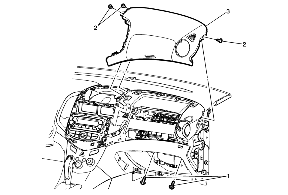
1 |
Instrument Panel Inflatable Restraint Module Fasteners (Qty:?€‰2) Caution: Refer to Fastener Caution.
10Y 89?€‰lb?€‰in |
|
2 |
Instrument Panel Upper Trim Panel Fastener (Qty:?€‰3) |
|
3 |
Instrument Panel Upper Trim Panel Procedures
|
 Instrument Panel Upper Trim Panel Replacement - Left Side
Instrument Panel Upper Trim Panel Replacement - Left Side
Callout
Component Name
Preliminary Procedure
Remove the instrument cluste ...
 Instrument Panel Knee Bolster Replacement
Instrument Panel Knee Bolster Replacement
Callout
Component Name
Preliminary Procedures
Disable the SIR system. Refer to SIR Disabl ...
Other materials:
OnStar Overview
If equipped, this vehicle has a comprehensive, in-vehicle system that can connect
to a live Advisor for Emergency, Security, Navigation, Connection, and Diagnostic
Services.
The OnStar system status light is next to the OnStar buttons. If the status light
is:
Solid Green: System is ...
Liftgate Weatherstrip Replacement
Liftgate Weatherstrip Replacement
Callout
Component Name
1
Liftgate Weatherstrip
Procedure
Clean the area where the seal will be mounted. Use a suitable solvent
with a mixture of 50?€‰percent isopropyl alc ...
Transmission Mount Replacement - Left Side
Removal Procedure
Remove the battery tray. Refer to
Battery Tray Replacement.
Install the engine support fixture. Refer to
Engine Support Fixture.
Remove and DISCARD the left transmission mount to
bracket bolts (1).
Remove the left transmission mo ...

0.0086