Chevrolet Sonic Repair Manual: Piston, Connecting Rod, and Bearing Cleaning and Inspection
Special Tools
EN-470-B Angular Torque Wrench
For equivalent regional tools, refer to Special Tools.
- Visual Inspection And Cleaning Procedure
- Connecting Rod
- Clean the connecting rods in solvent and dry with compressed air.
- Inspect the connecting rod for the following:
Warning:
Wear safety glasses when using compressed air in order to prevent eye injury.
- Signs of being twisted, bent, nicked or cracked
- Scratches or abrasion on the connecting rod bearing seating surfaces
- Clean the piston with a cleaning solvent. DO NOT wire brush any parts of the piston.
- Clean the piston ring grooves.
- Inspect the piston on the following:
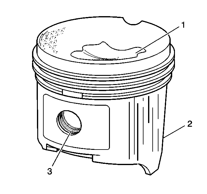
- Cracked ring lands, skirts or pin bosses
- Ring grooves for nicks
- Eroded areas on the top of the piston (1)
- Scuffed or damaged skirts (2)
- Worn piston pin bores (3)
- If there is any excessive wear, replace the piston.
- Measure the clearance between piston pin and piston bore.
- Piston And Connecting Rod Measurement Procedure
- Piston Ring Clearance
- Install the piston rings to the cylinder as shown (1) and measure the piston ring end gap. Compare the measurements with those provided below:
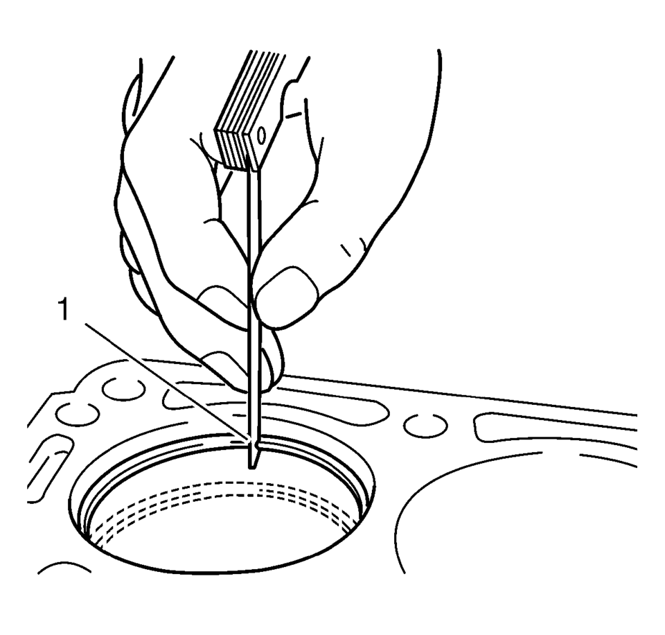
__
- The upper compression ring end gap should be 0.4?E.6 mm (0.0157?E.0236 in).
- The lower compression ring end gap should be 0.4?E.6 mm (0.0157?E.0236 in).
- The oil ring end gap should be 0.2?E.9 mm (0.0079?E.0354 in).
- If the clearance is greater than the provided specifications, the piston rings must be replaced.
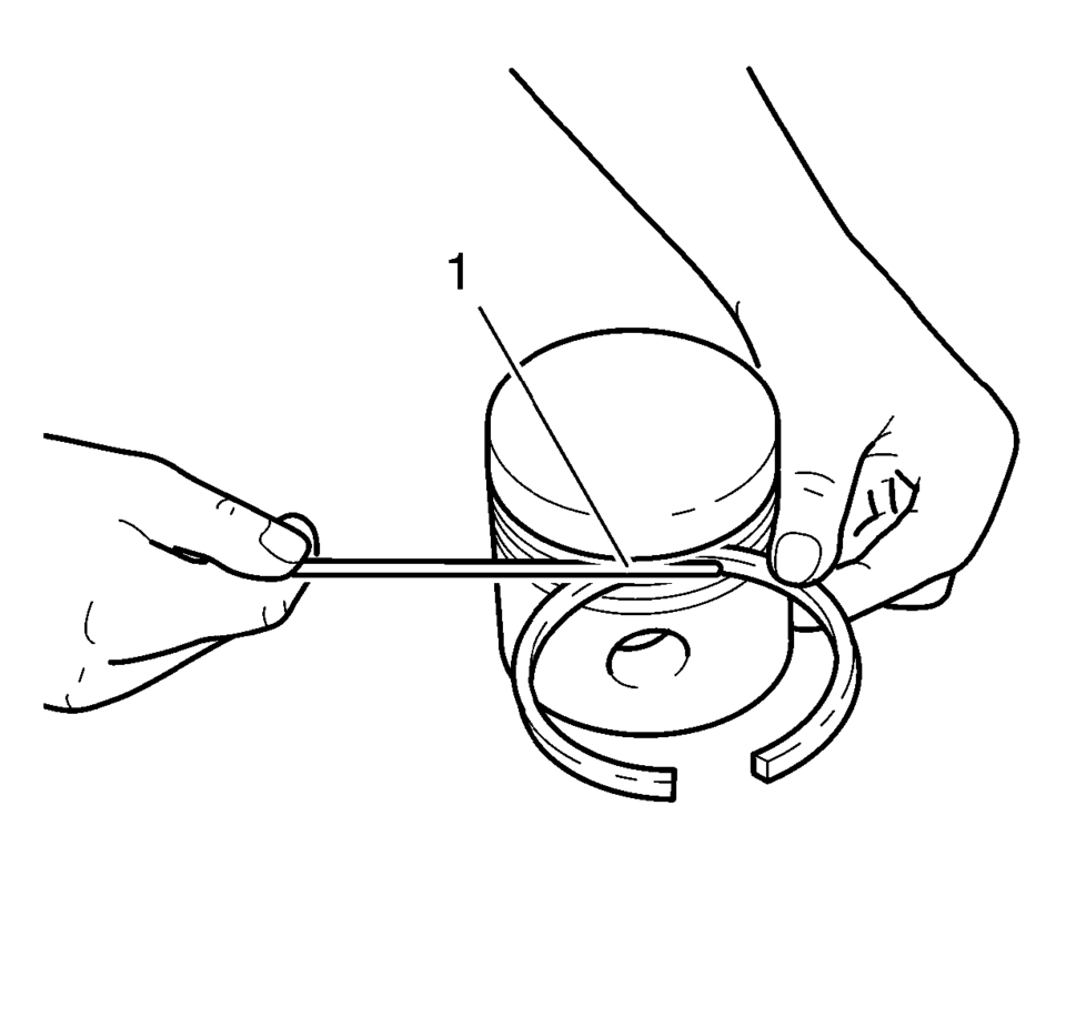
- Measure the piston ring side clearance as shown (1). Compare the measurements with those provided below:
- The upper compression ring side clearance should be 0.025?E.07 mm (0.001?E.0028 in).
- The lower compression ring side clearance should be 0.025?E.07 mm (0.001?E.0028 in).
- The oil ring side clearance should be 0.04?E.12 mm (0.0016?E.0047 in).
- If the clearance is greater than the provided specifications, replace the piston rings.
- If the clearance is still to great, replace the pistons.
Connecting Rod Bearing Clearance (With Micrometer Gauge Internal Measuring Device)- Install the connecting bearings and the connecting rod bearing caps.
- Tighten the connecting rod bearing cap bolts in the following sequence:
- Tighten the connecting rod bearing cap bolts to 10 Y (89 lb in)
.
- Tighten the bolts to an additional 60 degrees using EN-470-B wrench.
- Tighten the bolts to an additional 15 degrees using EN-470-B wrench.
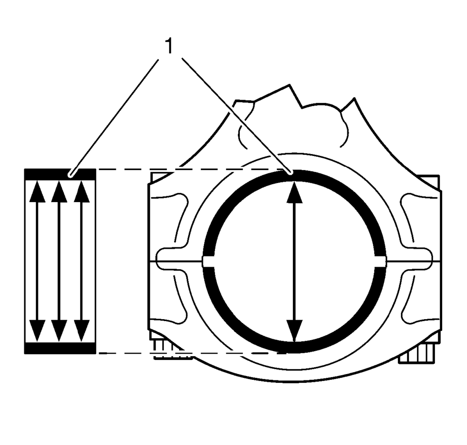
- Measure the connecting rod bearing diameters at 3 points as shown (1). Use a internal measuring device.
- Calculate the average connecting rod inner diameter.
Formula: 1. result + 2. result + 3. result / 3
- Measure the connecting rod journal diameter at 2 points between (1) and (3) and between (2) and (4). Use a micrometer gauge.
- Calculate the average connecting rod journal diameter.
Formula: 1. result + 2. result / 2.
- Substract the average connecting rod journal diameter from the average
connecting rod bearing diameter in order to determine the connecting rod
bearing clearance.
The clearance should be 0.013?E.061 mm (0.0005?E.0024 in)
.
Caution:
Refer to Fastener Caution
Note:
The old bolts can be reused for the measuring procedure.
 Piston and Connecting Rod Disassemble
Remove the piston with connection rod. Refer to Piston, Connecting Rod,
and Bearing Removal.
Note: Note installation position of the piston in respect of the
connection rod.
...
 Piston, Connecting Rod, and Bearing Installation
Special Tools
EN-470-B Angular Torque Wrench
For equivalent regional tools, refer to Special Tools.
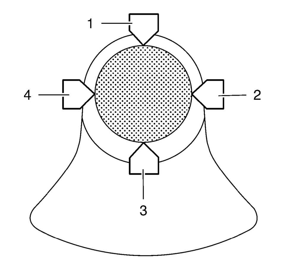
Adjust the piston ring joints as follows:
Upper compression ring (1).
...
Other materials:
SIR Seatbelt Pretensioner Handling Warning
Warning: When carrying an undeployed inflatable restraint seat belt
retractor pretensioner:
Do not carry the seat belt pretensioner by the seat belt webbing or
pigtail connector, if equipped.
Carry the seat belt pretensioner by the housing, keeping hands and fingers
away fro ...
Front Seat Belt Anchor Plate Tensioner Cover Replacement (4 Way)
Front Seat Belt Anchor Plate Tensioner Cover Replacement
Callout
Component Name
1
Driver or Passenger Seat Belt Tensioner Cover
Procedure
Remove the tensioner cover by pushing downward on the rear and center
o ...
System maintenance (ProPILOT Assist 2.1)
To ensure optimal performance of the Nissan Armada ProPILOT Assist 2.1 system,
it is essential to keep the driver monitor area clean and unobstructed at all times.
Carefully remove any dust, dirt, or smudges using a clean, soft cloth such as
a lens-cleaning cloth. Maintaining a clear camera ...

0.0061