Chevrolet Sonic Repair Manual: Rear Brake Cylinder Overhaul
- Disassembly Procedure
-
- Raise and support the vehicle. Refer to Lifting and Jacking the Vehicle.
- Remove the rear brake cylinder. Refer to Rear Brake Cylinder Replacement.
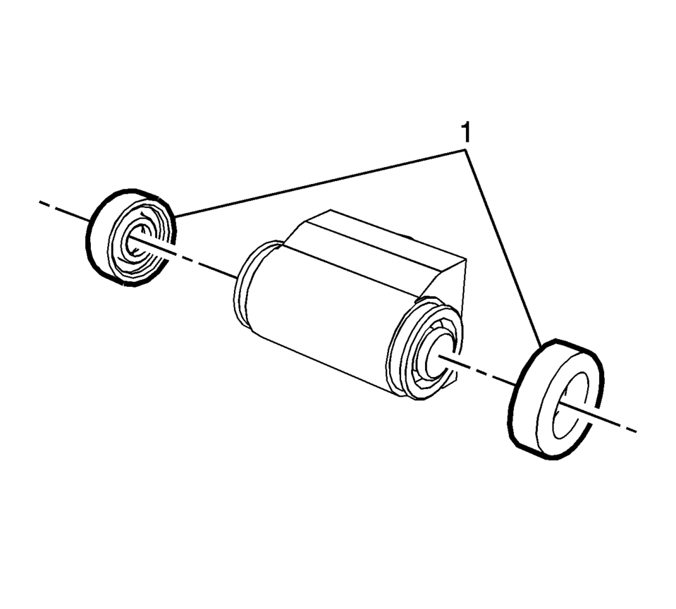
- Remove and discard the brake cylinder dust seals (1).
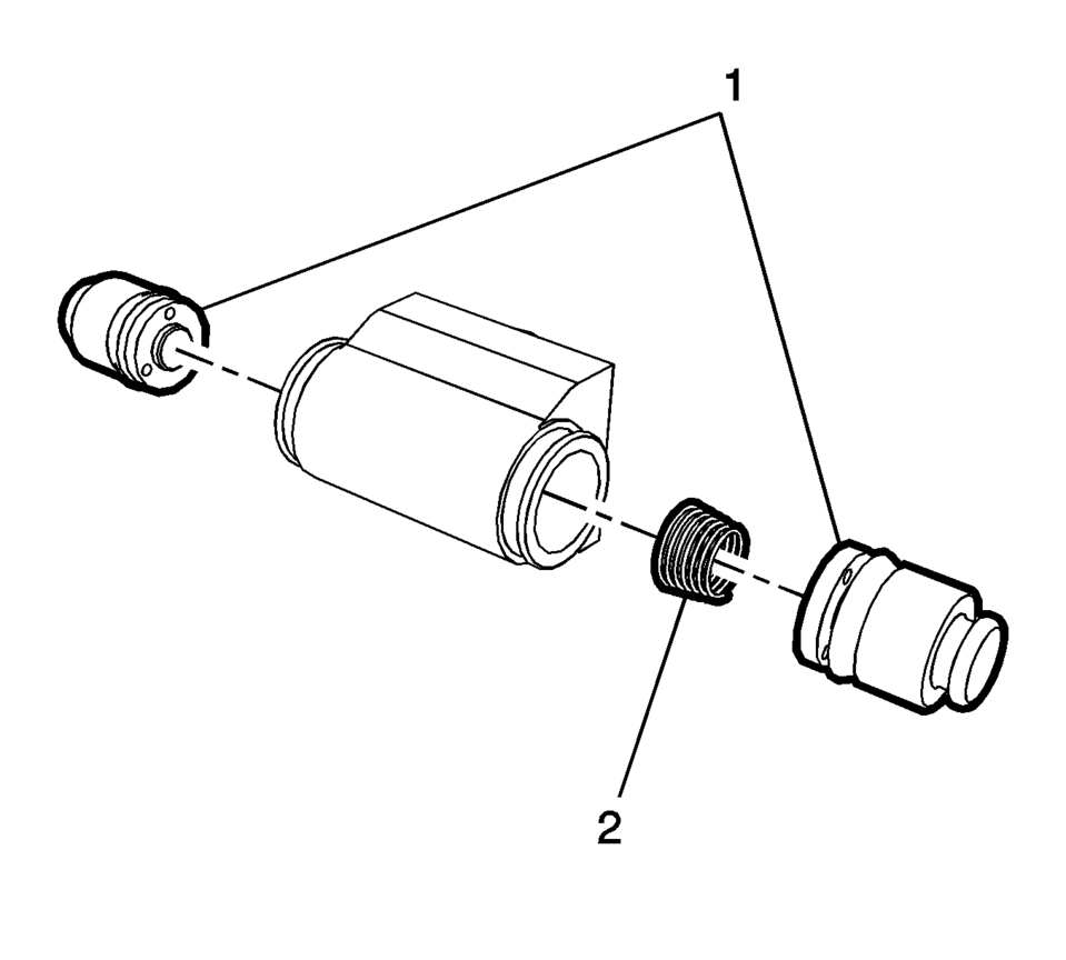
- Remove the brake cylinder pistons (1) and spring (2).
- Remove and discard the brake cylinder piston seals.
- Inspect the brake cylinder bore for excessive corrosion, scoring, nicks, and pitting.
- If the brake cylinder bore exhibits the above conditions, the brake cylinder assembly requires replacement.
- Remove light corrosion in the cylinder bore with a fine crocus cloth.
- Thoroughly clean the brake cylinder and pistons with denatured alcohol and dry with filtered, non-lubricated compressed air.
Warning:
Refer to Brake Dust Warning.
Warning:
Refer to Brake Fluid Irritant Warning.
- Assembly Procedure
-
- Lightly lubricate the new piston seals and brake cylinder bore with GM approved brake fluid from a clean, sealed, brake fluid container.
- Assemble the new piston seals with the lip of the seals facing inward to the brake cylinder pistons.
- Install the brake cylinder pistons (1) and spring (2) into the brake cylinder bore.
- Install the new brake cylinder dust seals (1).
- Install the rear brake cylinder. Refer to Rear Brake Cylinder Replacement.
- Bleed the hydraulic brake system. Refer to Hydraulic Brake System Bleeding.
Note:
Do not lubricate the brake cylinder dust seals.
 Rear Brake Backing Plate Replacement
Removal Procedure
Warning: Refer to Brake Dust Warning.
Raise and support the vehicle. Refer to Lifting and Jacking the Vehicle.
Remove the tire and wheel assembly. Refer ...
 Rear Brake Cylinder Replacement
Removal Procedure
Warning: Refer to Brake Dust Warning.
Warning: Refer to Brake Fluid Irritant Warning.
Raise and support the vehicle. Refer to Lifting and Jacki ...
Other materials:
Radio Windshield Side Garnish Molding Speaker Replacement
Radio Windshield Side Garnish Molding Speaker Replacement
Callout
Component Name
Preliminary Procedure
Remove the windshield side garnish molding. Refer to
Windshield Side Garnish Molding Replacement.
1
...
Rear Suspension Description and Operation
This vehicle has a beam rear suspension system consisting of the following components:
An axle with integral trailing arms
A cross beam
Two coil springs
Two standard shock absorbers
Axle Assembly
The axle assembly attaches to the underbody through a rubber bushing and
brac ...
Drive and Driven Sprocket, Drive Link, and Park Pawl Installation (6T30)
Drive and Driven Sprocket, Drive Link, and Park Pawl Installation
Callout
Component Name
1
Front Differential Carrier Baffle
2
Baffle Retainer
3
Front Differential ...

0.0057