Chevrolet Sonic Repair Manual: Steering Gear Boot Replacement
Special Tools
CH-804 Tensioner
For equivalent regional tools, refer to Special Tools.
- Removal Procedure
-
- Raise and support the vehicle. Refer to Lifting and Jacking the Vehicle.
- Remove the steering linkage outer tie rod. Refer to Steering Linkage Outer Tie Rod Replacement.
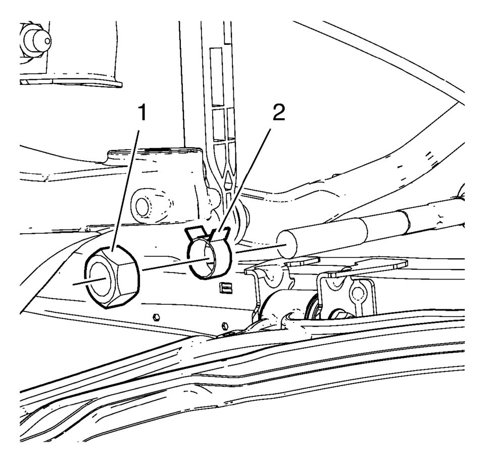
- Remove the steering linkage inner tie rod nut (1).
- Remove the steering gear boot outer clamp (2).
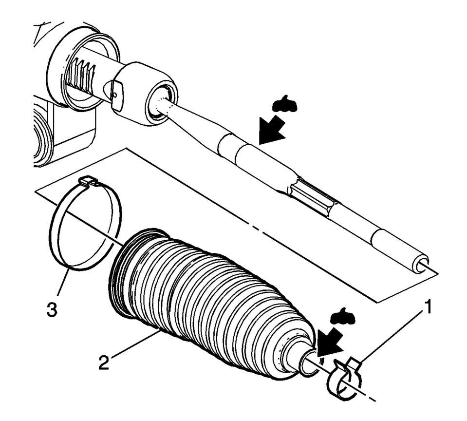
- Remove the steering gear boot inner clamp (3). Discard the clamp.
- Remove the steering gear boot (2).
- Clean the steering linkage inner tie rod and the steering gear boot contact area of any lubricant or debris.
Note:
Place match marks on the steering linkage inner tie rod nut and the steering linkage inner tie rod before removing. During installation of the nut, align the match marks.
- Installation Procedure
-
- Install a new steering gear boot inner clamp (3) loosely on the steering gear boot (2).
- Apply the lubricant from the service kit to the steering linkage inner tie rod and to the steering gear boot (2).
- Install the steering gear boot (2) over the steering linkage inner tie rod and onto the steering gear.
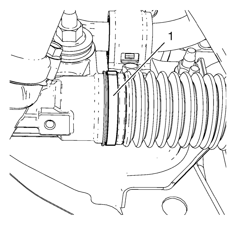
- Use the CH-804 tensioner in order to crimp the inner steering gear boot clamp (1).
- Install the steering gear outer boot clamp (2).
- Install the steering linkage inner tie rod nut (1).
- Install the steering linkage outer tie rod. Refer to Steering Linkage Outer Tie Rod Replacement.
- After installation is complete, measure and adjust the front toe. Refer to Wheel Alignment - Steering Wheel Angle and/or Front Toe Adjustment.
Note:
The steering gear boot must seat in the appropriate groove on the steering gear.
 Special Tools
Illustration
Tool Number/ Description
CH-161-B
DT-161-B
KM-161-B
J-22888-20A
Bearing Puller
...
 Steering Gear Replacement
Steering Gear Replacement
Callout
Component Name
Caution: With wheels of the vehicle facing straight ahead,
secure the st ...
Other materials:
Fuel Tank Filler Door Replacement
Fuel Tank Filler Door Replacement
Callout
Component Name
1
Fuel Tank Filler Door
Procedure
Position the fuel tank filler door to the full open position. Using light
outward sliding pressure on the filler door, ...
Fuel Tank Filler Pipe Replacement
Removal Procedure
Remove the bracket fastener (1).
Lift and support the vehicle. Refer to
Lifting and Jacking the Vehicle.
Remove the fuel tank filler pipe bracket fastener (1).
Disconnect the vent hose (2). Refer to
Plastic Collar ...
Engine Coolant Temperature Sensor Replacement - Radiator
Engine Coolant Temperature Sensor Replacement - Radiator
Callout
Component Name
Preliminary Procedure
Drain the cooling system. Refer to
Cooling System Draining and Filling.
Remove the right front wheelhouse liner. Ref ...

0.0078