Chevrolet Sonic Repair Manual: Transmission Assemble (Gen 2)
Special Tools
- 3-9506289 Universal Adapter
- R-0007758 Holding Fixture
- S-9407197 Differential Rotating Tool
- S-9407198 Differential Bearing Race Wrench
For equivalent regional tools, refer to Special Tools.
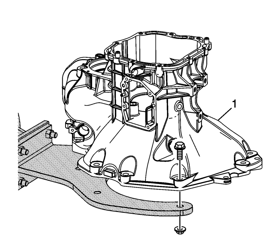
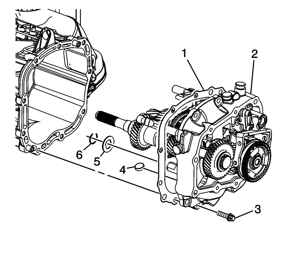
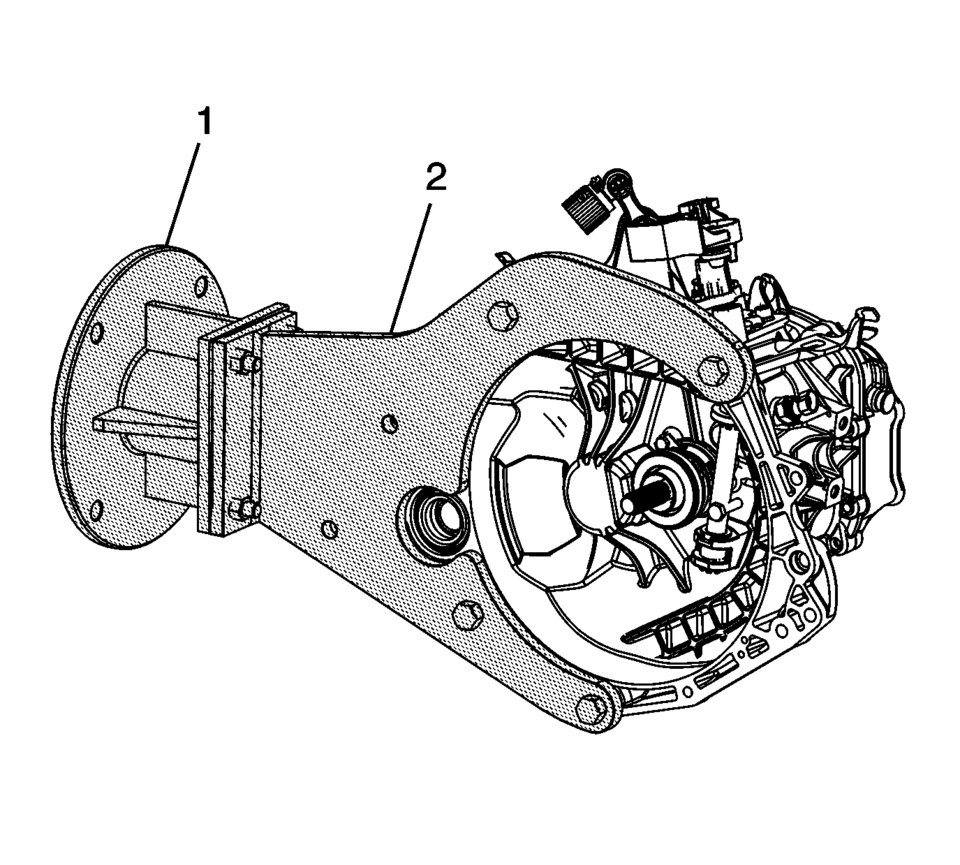
- Install the clutch and differential housing assembly (1) onto the R-0007758 holding fixture.
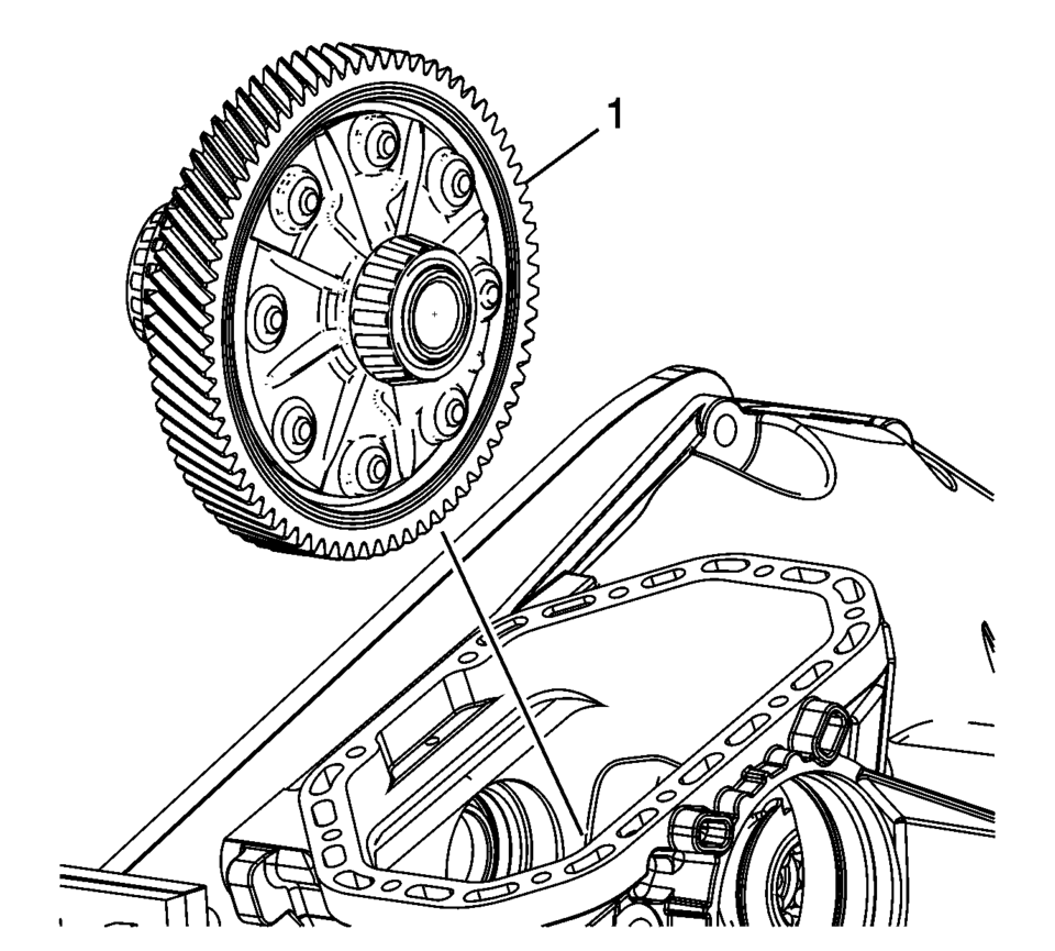
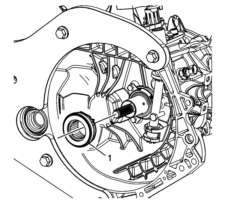
- Install the front differential carrier (1).
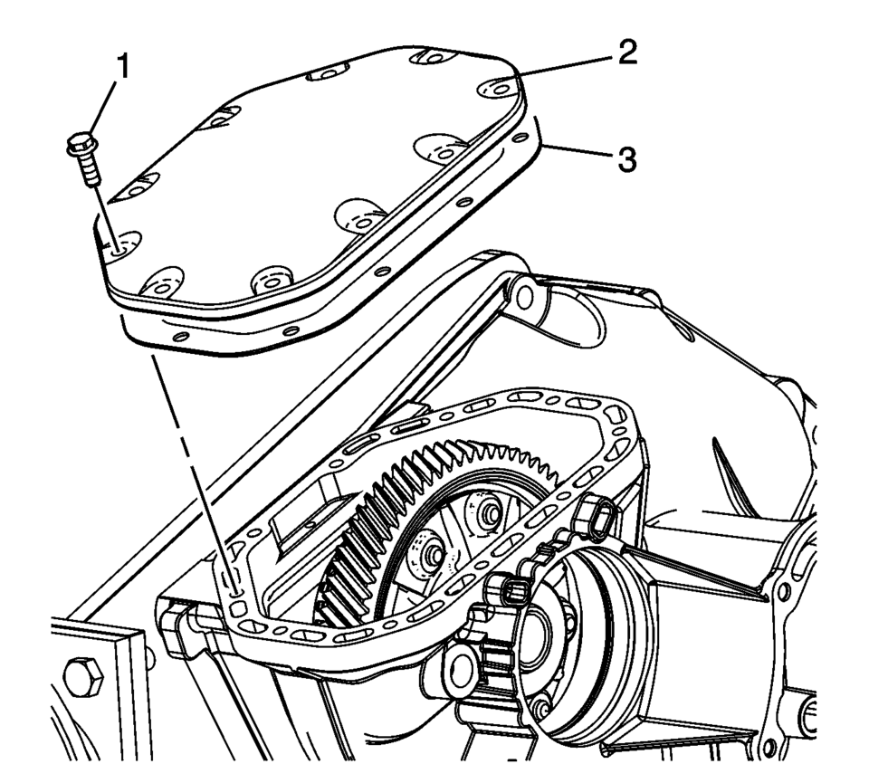
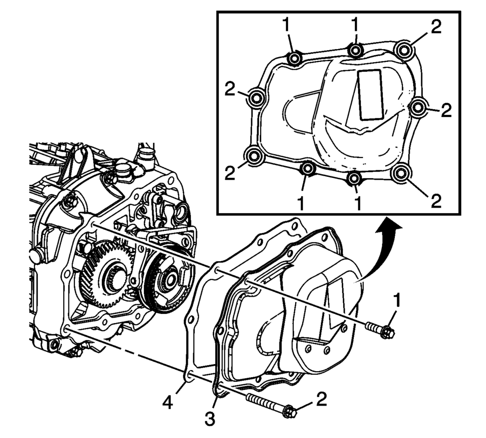
- Install the gasket (3) and differential carrier cover (2).
- Install the front differential carrier cover bolts (1).
Tighten to 7 Y (61.96 lb in)
.
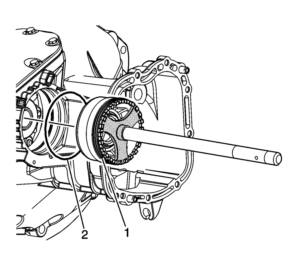
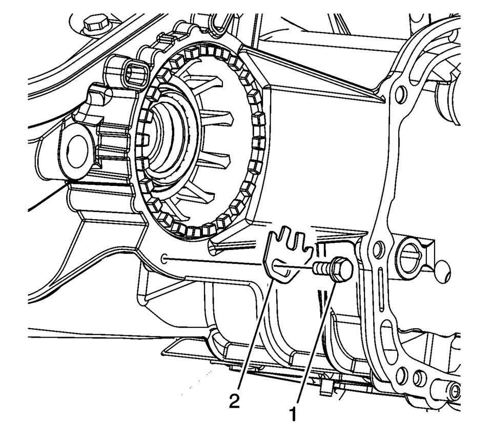
- Lubricate the O-ring seal (2) with multipurpose grease and install onto the differential bearing adjuster (1).
- Lubricate the threads on the differential bearing adjuster with multipurpose grease.
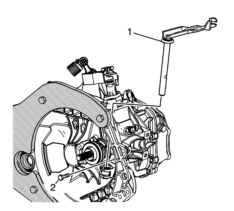
- Using S-9407198 differential bearing race wrench install the front differential bearing adjuster (1).
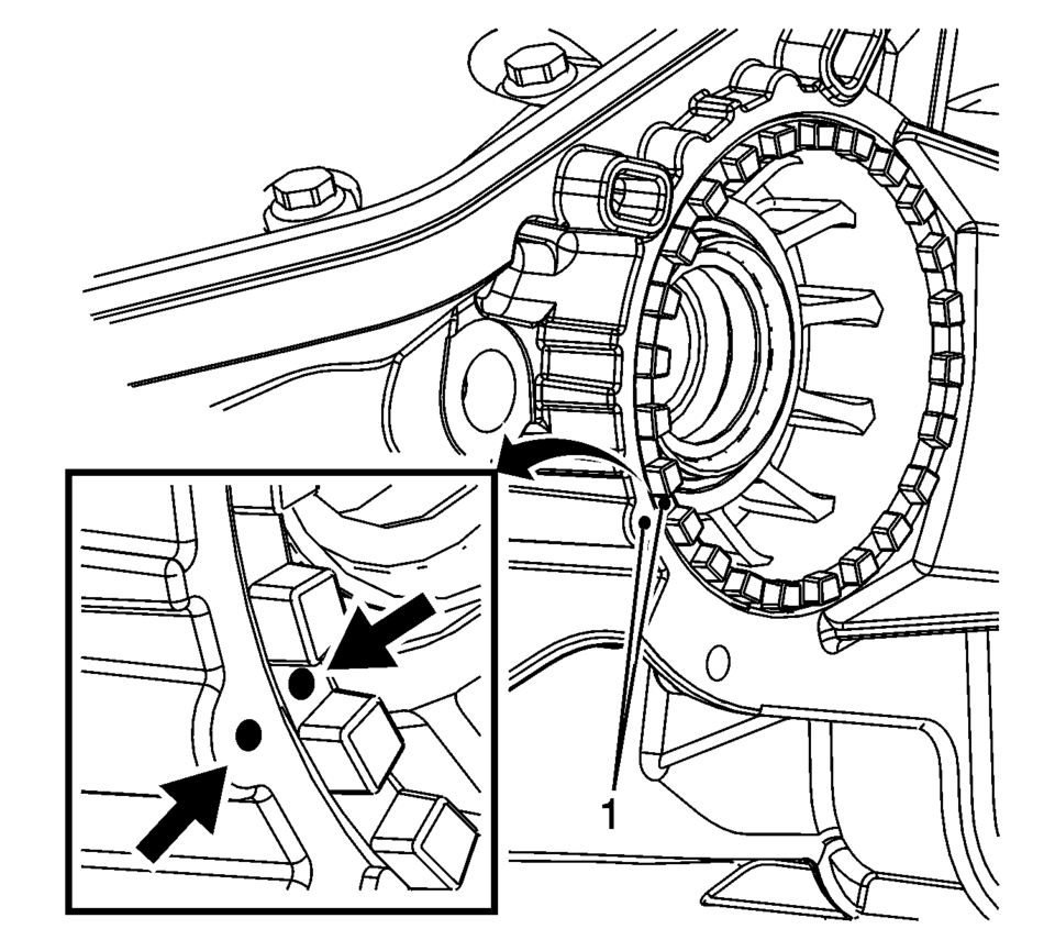
- Align marks on the differential bearing adjuster and case (1).
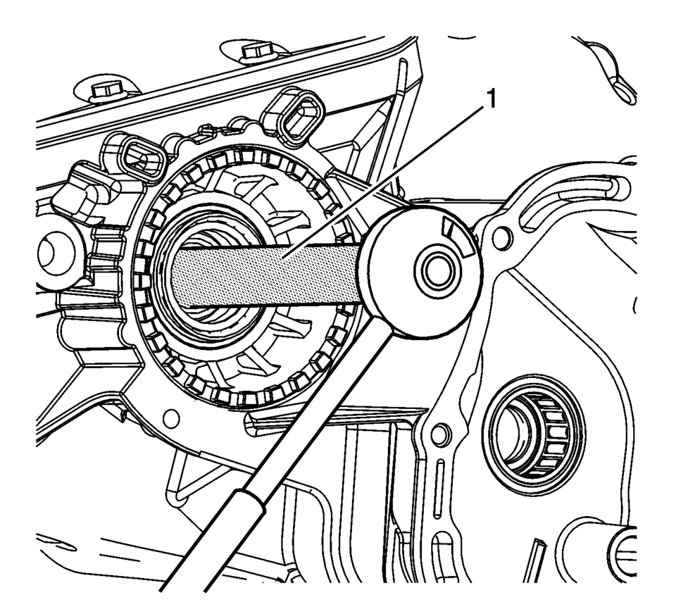
- Using the S-9407197 differential rotating tool and a torque wrench, rotate the differential (1) 1 revolution per second.
- The breakaway bearing torque should be:
Note:
If all the components are re-used align adjuster to marks. If any component was replaced go to the next step.
Note:
If no components were replaced, the bearing adjuster can be aligned to the marks. If any component was replaced, the following procedure must be performed.
- Re-use bearing ?#8201;60?00 Ncm
- New Bearing ?#8201;150?10 Ncm
.
.
Note:
The reverse gear shaft snap ring (6) MUST be installed even if not originally equipped to prevent shifting issues caused by incorrect assembly or parts not in position.
.
.
.
.
.
 Transmission Assemble (Gen 1)
Special Tools
3-9506289 Universal Adapter
R-0007758 Holding Fixture
S-9407197 Differential Rotating Tool
S-9407198 Differential Bearing Race Wrench
For equivalent regional tools, refer ...
 Transmission Case Assemble (Gen 1)
Special Tools
3-9506289 Universal Adapter
J-840733 Driver
R-0007758 Holding Fixture
R-0007761 Universal Handle
R-0007770 Holding Fixture Adapter Plates
T-9804669 Seal Installer
T-0 ...
Other materials:
Front Wheelhouse Liner Replacement (Rear)
!l
Front Wheelhouse Liner Replacement
Callout
Component Name
Preliminary Procedure
Remove the tire and wheel assembly. Refer to Tire and Wheel Removal and
Installation.
1
Front Wheelhouse Rear Li ...
Heater Core Outlet Tube Replacement
Heater Core Outlet Tube Replacement
Callout
Component Name
Preliminary Procedures
Remove the Heater and Air Conditioning Evaporator and Blower Module.
Refer to Heater and Air Conditioning Evaporator and Blower Module Removal
...
HomeLink Universal Transceiver
Basic information
The HomeLink Universal Transceiver in the Nissan Armada offers a practical and
streamlined solution by combining the functions of up to three separate handheld
remote controls into one integrated system.
With the Nissan Armada HomeLink system, you can conveniently operate a w ...

0.0069