Chevrolet Sonic Repair Manual: Front Brake Caliper Bracket Replacement
- Removal Procedure
-
Warning:
Refer to Brake Dust Warning.
- Raise and support the vehicle. Refer to Lifting and Jacking the Vehicle.
- Remove the tire and wheel assembly. Refer to Tire and Wheel Removal and Installation.
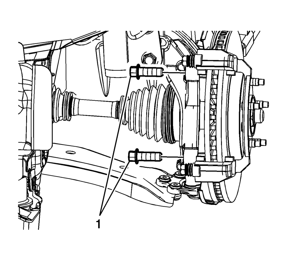
- DO NOT use any air tools to remove or install the guide pin bolts. Use hand tools ONLY.
- Install an open end wrench to hold the caliper guide pin in line with the brake caliper while removing or installing the caliper guide pin bolt. DO NOT allow the open end wrench to come in contact with the brake caliper. Allowing the open end wrench to come in contact with the brake caliper will cause a pulsation when the brakes are applied.
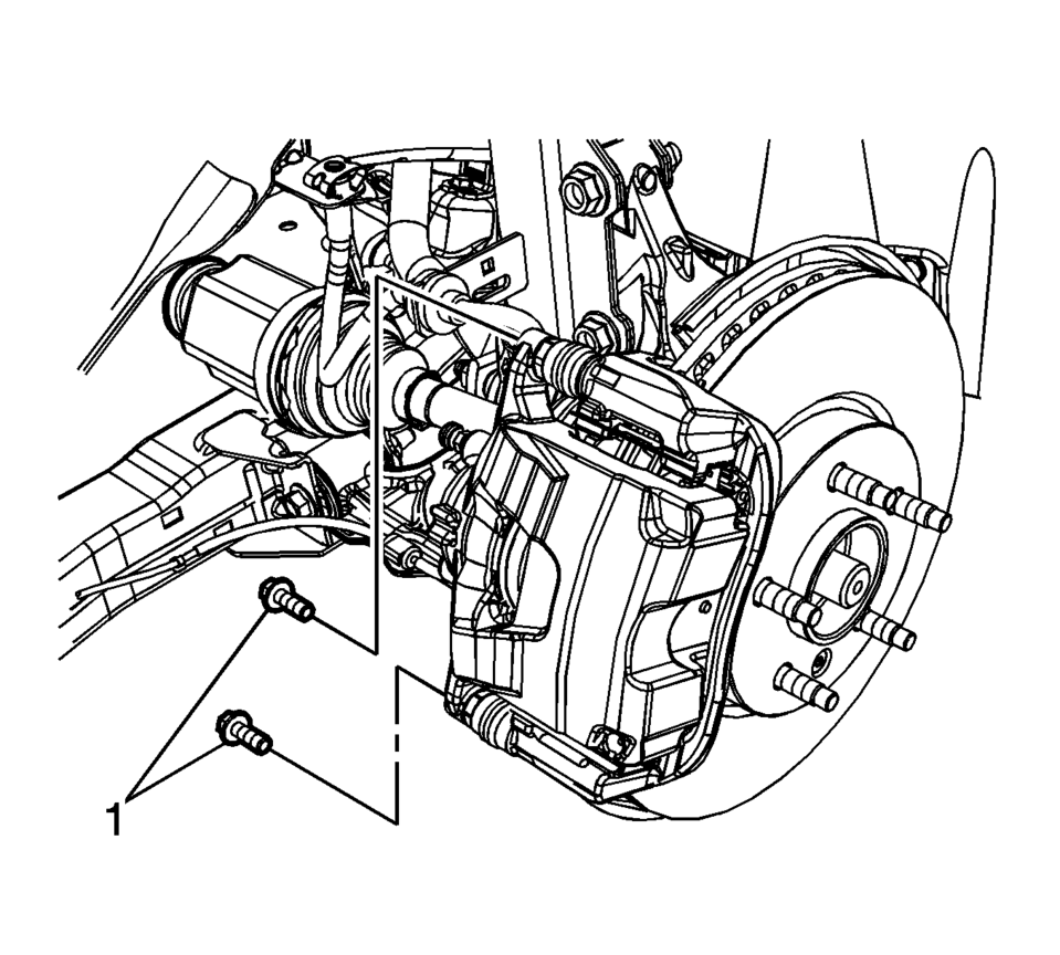
- Hold the brake caliper guide pin stationary and remove the brake caliper guide pin bolts (1).
- Remove the brake caliper and support with heavy mechanics wire or equivalent.
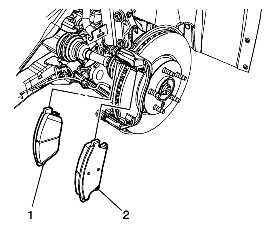
- Remove the inner brake pad (1).
- Remove the outer brake pad (2).
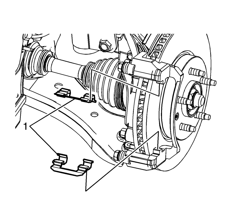
- Remove the brake pad springs (1).
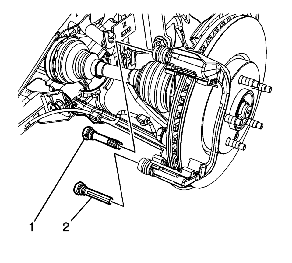
- Remove the upper brake caliper guide pin (1).
- Remove the lower brake caliper guide pin (2).
- Remove the 2 brake caliper guide pin seals.
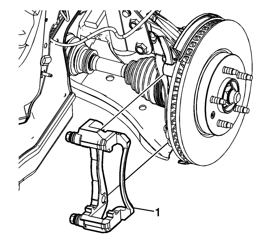
- Remove and discard the brake caliper bracket bolts (1).
- Remove the brake caliper bracket (1).
Note:
Caution:
Support the brake caliper with heavy mechanic wire, or equivalent, whenever it is separated from its mount and the hydraulic flexible brake hose is still connected. Failure to support the caliper in this manner will cause the flexible brake hose to bear the weight of the caliper, which may cause damage to the brake hose and in turn may cause a brake fluid leak.
Note:
Note the location of the wear sensor for correct installation.
Note:
The upper brake caliper guide pin is equipped with a bushing and must be installed in the same location.
Note:
Do not reuse the brake caliper bracket bolts.
- Installation Procedure
-
- Install the brake caliper bracket (1).
- Install 2 new brake caliper bracket bolts (1) and tighten to 100 Y
(74 lb ft)
.
- Install the brake pad springs (1).
- Install the 2 brake caliper guide pin seals.
- Ensure the brake caliper guide pin seals are fully seated in the groove of the brake caliper bracket.
- Install the upper brake caliper guide pin (1).
- Install the lower brake caliper guide pin (2).
- Ensure the brake caliper guide pin seals are fully seated in the groove of the brake caliper guide pins.
- Install the inner brake pad (1).
- Install the outer brake pad (2).
- Position the brake caliper over the brake pads and to the caliper bracket.
- Using a backup wrench to hold the brake caliper guide pin stationary,
install the brake caliper guide pin bolts (1) and tighten to 28 Y (21 lb ft)
.
- Install the tire and wheel assembly. Refer to Tire and Wheel Removal and Installation.
Caution:
Refer to Fastener Caution.
Note:
The upper brake caliper guide pin is equipped with a bushing and must be installed in the same location.
Note:
Note the location of the wear sensor for correct installation.
 Brake Caliper Inspection
Warning: Refer to Brake Dust Warning.
Inspect the brake caliper housing (1) for cracks, excess wear, and/or damage.
If any of these conditions are present, the brake calipe ...
 Front Brake Caliper Overhaul
Disassembly Procedure
Warning: Refer to Brake Dust Warning.
Warning: Refer to Brake Fluid Irritant Warning.
Warning: Do not place fingers in front of the caliper ...
Other materials:
TPMS Sensor Matching Process
Each TPMS sensor has a unique identification code. The identification code needs
to be matched to a new tire/wheel position after rotating the tires or replacing
one or more of the TPMS sensors. The TPMS sensor matching process should also be
performed after replacing a spare tire with a road ...
Radio Antenna Base Replacement
Radio Antenna Base Replacement
Callout
Component Name
Preliminary Procedure
Lower the rear of the headlining trim panel. Refer to
Headlining Trim Panel Replacement.
1
Radio Antenna Base Fastener
...
Thrust Washer and Bearing Cleaning and Inspection
Warning: Wear safety glasses to avoid injury when using compressed
air or any cleaning solvent. Bodily injury may occur if fumes are inhaled
or if skin is exposed to chemicals.
Caution: Do not allow the bearings to spin. Turn them slowly by
hand. Spinning the beari ...

0.0049