
Chevrolet Sonic Repair Manual: Starter Replacement (LUW)
- Removal Procedure
-
- Disconnect the negative battery cable. Refer to Battery Negative Cable Disconnection and Connection.
- Raise and support the vehicle. Refer to Lifting and Jacking the Vehicle.
- Remove the drivetrain and front suspension frame skid plate. Refer to Drivetrain and Front Suspension Frame Skid Plate Replacement.
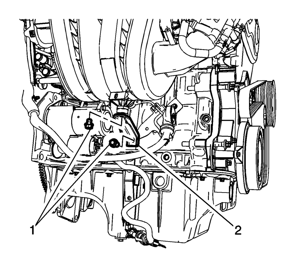
- Remove the intake manifold brace fasteners (1) and remove the intake manifold brace (2).
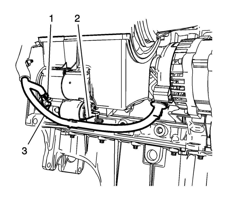
- Remove the starter solenoid battery positive fastener (2) and the starter mounting stud/fastener (1).
- Remove the battery positive and negative cable (3) from the starter.
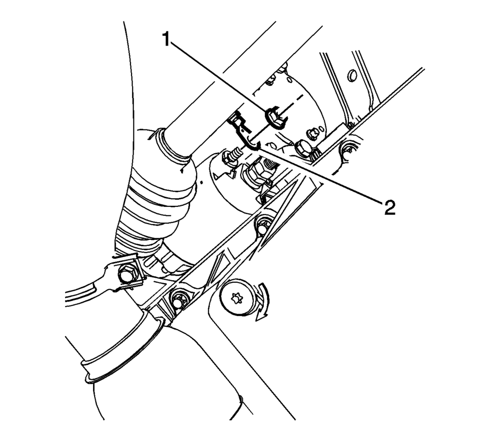
- Remove the starter solenoid fastener (1) and the engine harness terminal (2) from the starter solenoid.
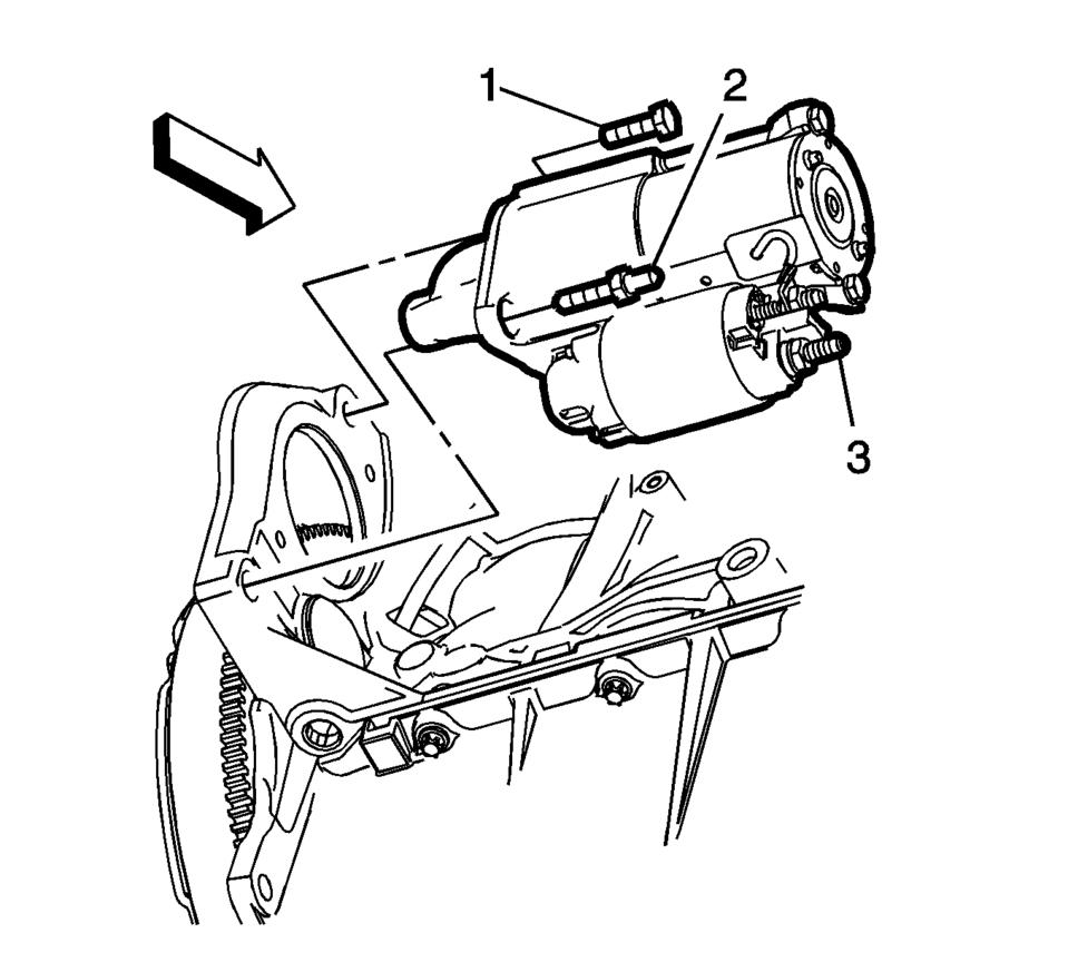
- Remove the starter mounting fastener (1) and the starter (3) from the vehicle.
Note:
The starter mounting fastener can be accessed from the top of the engine, with the battery tray removed.
- Installation Procedure
-
- Install the starter (3) into position and tighten the starter mounting
fastener (1) to 25 Y (18 lb ft)
.
- Install the engine harness terminal (2) to the starter solenoid and
tighten the solenoid fastener (1) to 9 Y (80 lb in)
.
- Install the battery negative cable terminal and the starter mounting
stud/fastener (1) to the starter. Tighten to 25 Y (18 lb ft)
.
- Install the positive battery cable terminal to the starter solenoid
and tighten the fastener (2) to 9 Y (80 lb in)
.
- Install the intake manifold brace (2) and mounting fasteners (1). Tighten
to 8 Y (71 lb in)
.
- Install the drivetrain and front suspension frame skid plate. Refer to Drivetrain and Front Suspension Frame Skid Plate Replacement.
- Connect the negative battery cable. Refer to Battery Negative Cable Disconnection and Connection.
Caution:
Refer to Fastener Caution.
- Install the starter (3) into position and tighten the starter mounting
fastener (1) to 25 Y (18 lb ft)
 Starter Replacement (LUV)
Removal Procedure
Disconnect the battery negative cable. Refer to Battery Negative Cable
Disconnection and Connection.
Raise and support the vehicle. Refer to Lifting and J ...
 Starting System Description and Operation
The starter motors are non-repairable starter motors. They have pole pieces that
are arranged around the armature. Both solenoid windings are energized. The pull-in
winding circuit is completed to ...
Other materials:
Rear Compartment Side Trim Replacement - Left Side (Sedan)
Rear Compartment Side Trim Replacement - Left Side
Callout
Component Name
Preliminary Procedures
Remove the rear compartment floor panel carpet. Refer to Rear Compartment
Floor Panel Carpet Replacement.
Remove the rear co ...
Camshaft Timing Chain Adjustment
Special Tools
EN-952 Fixing Pin
EN-953–A Fixing Tool
EN-49977?E00 Fixation Sensor Discs
For equivalent regional tools, refer to Special Tools.
Remove the ignition coil. Refer to Ignition Coil Replacement.
Remove the camshaft cover. Refer to Camshaft Cover Replacement.
Remove ...
System maintenance (ProPILOT Assist 2.1)
For reliable and accurate operation of the Nissan Armada ProPILOT Assist 2.1
system, it is crucial to keep the driver monitoring area clean and free from any
obstruction at all times.
Regularly inspect the camera surface and gently remove dust, fingerprints, or
any debris using a soft, cl ...

0.0054